X-ray CT apparatus, method of aligning phantom, and phantom retaining tool

a technology of phantom retaining tool and computed tomography, which is applied in the field of x-ray ct (computed tomography) apparatus, can solve the problems of difficult operation, heavy burden on operators, and operators who do not improve their skill with experience, and achieve the effect of simplifying the operation of alignment and high precision

Active Publication Date: 2011-01-11
TOSHIBA MEDICAL SYST CORP
View PDF22 Cites 12 Cited by
  • Summary
  • Abstract
  • Description
  • Claims
  • Application Information

AI Technical Summary

Benefits of technology

[0015]The objective of the present invention is intended to solve the above-mentioned problems by providing technology that enables a phantom to quickly and easily be aligned, regardless of the level of skill of the operator.
[0016]Moreover, another objective of the present invention is intended to provide technology that enables a phantom to be aligned with high precision in a simple alignment operation.

Problems solved by technology

With the conventional method of setting a phantom, because the distance to move the phantom is visually specified by the operator, it is difficult to set a phantom in the targeted position with one attempt of the above-described serial operation, and this serial operation is normally repeated many times. Therefore, the operation of setting a phantom becomes a prolonged process, which is a heavy burden on the operator.
Therefore, it can be relatively quick for a skilled operator to grasp a direction and distance of movement, but for operators who are not as skilled, such an operation is difficult.
In addition, this kind of operation depends upon the sense of the operator, and some operators do not improve their skill with experience.
Thus, when such a method is used, the operation of matching the cylinder axis of the phantom with the center of the scan must be manually performed beforehand, so time and effort are required.
Moreover, these hitherto known inventions had the problem of being unable to confirm whether the phantom is positioned at the center of the scan.
In the actual positioning operation, the phantom could lean horizontally, but it could not be handled by the existing inventions.

Method used


Image

  • X-ray CT apparatus, method of aligning phantom, and phantom retaining tool
  • X-ray CT apparatus, method of aligning phantom, and phantom retaining tool
  • X-ray CT apparatus, method of aligning phantom, and phantom retaining tool

Examples


first embodiment

Overall Composition of Apparatus

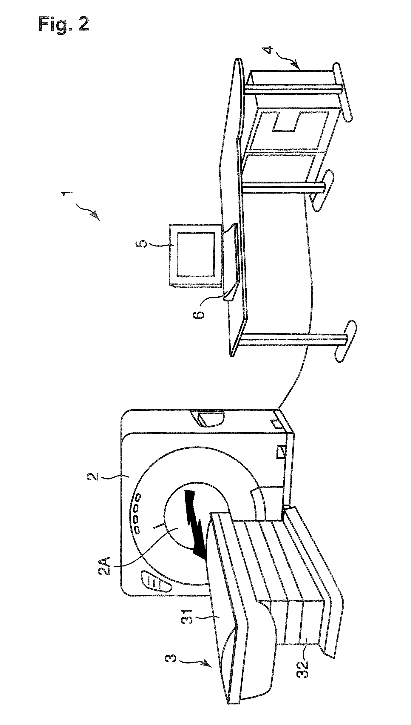
[0057]The overall composition of X-ray CT apparatus related to the first embodiment of the invention will be described with reference to FIG. 2 and FIG. 3. FIG. 2 shows the appearance of the composition of the X-ray CT apparatus 1 related to the embodiment. Moreover, FIG. 3 shows an internal composition of the X-ray CT apparatus 1. The X-ray CT apparatus 1 related to the embodiment is as is conventionally comprised, including a gantry 2, bed 3, computer apparatus 4, monitor 5, and input device 6.

[0058]The monitor 5 and input device 6 are used as the console 7 of the X-ray CT apparatus 1 (refer to FIG. 3). The monitor 5 relates to an example of the “display device” of the invention, and consists of arbitrary display apparatus such as an LCD (liquid crystal display) or a CRT (cathode ray tube). The input device 6 consists of arbitrary input apparatus such as a keyboard, mouse, track ball, control panel, or a touch panel.

[0059]The gantry 2 has a built-in...

modified embodiment 1

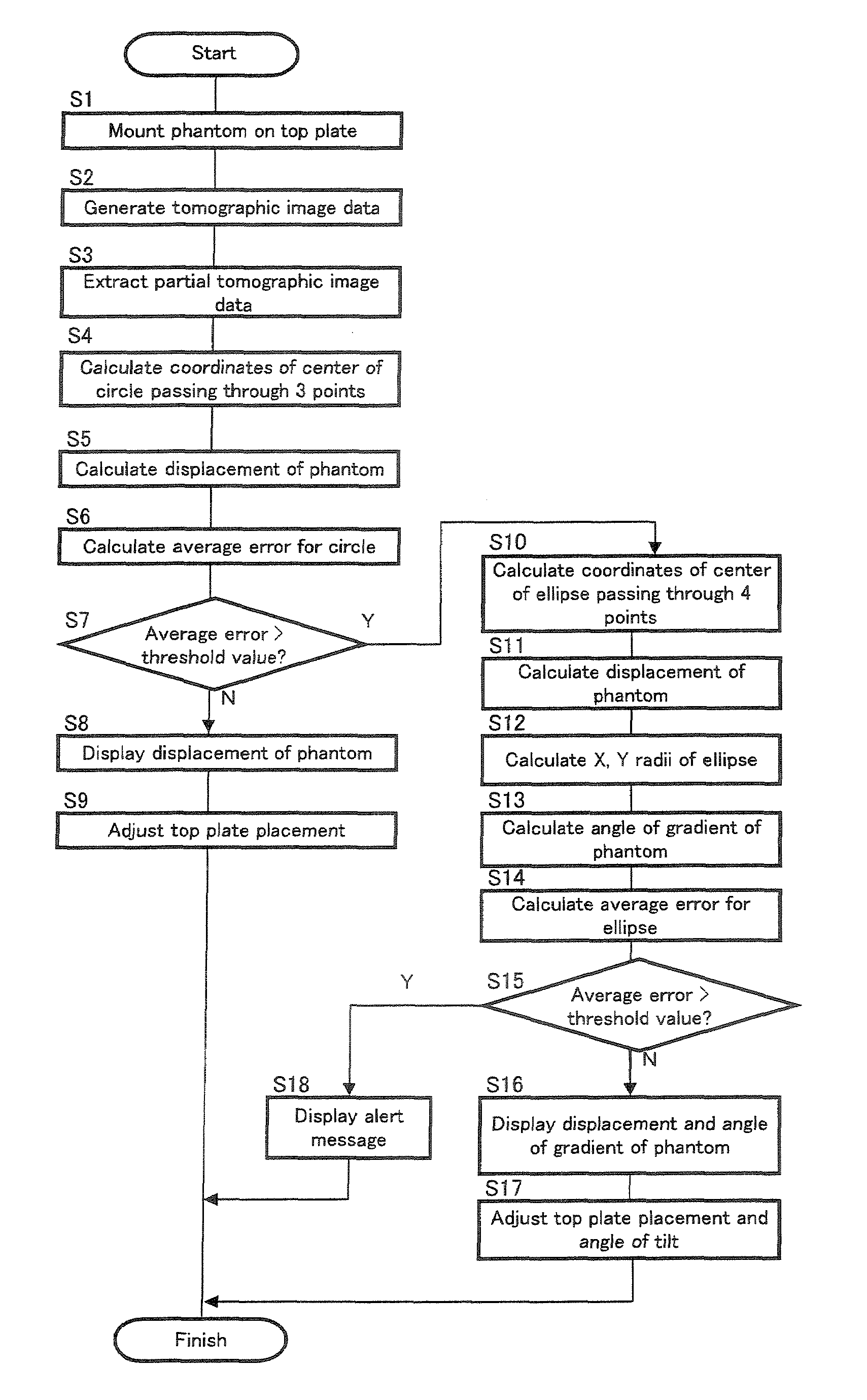
[0166]When a gradient of the phantom 100 is significant level (S7; Y), a message to indicate that the phantom 100 tilts or to encourage a correction of the gradient may be displayed on the monitor 5. By referring to the warning message, the operator can recognize that the phantom 100 tilts in no small measure, and also the necessity for correction of it. Thereby, the operation can be eased and accelerated.

[0167]The warning message displayed when a gradient of the phantom 100 is significant level (S7; Y) or when a tomographic image of the phantom 100 cannot considered as an ellipse (S15; Y), relates to an example of the “alarm information” of the invention. The alarm information is not limited to such warning message, and any form may be applied as long as the above determination result can be made known by the information. The form may be visual information, such as by lighting (blinking) of a warning lamp, audio information such as a warning buzzer, and tactile information such as ...

modified embodiment 2

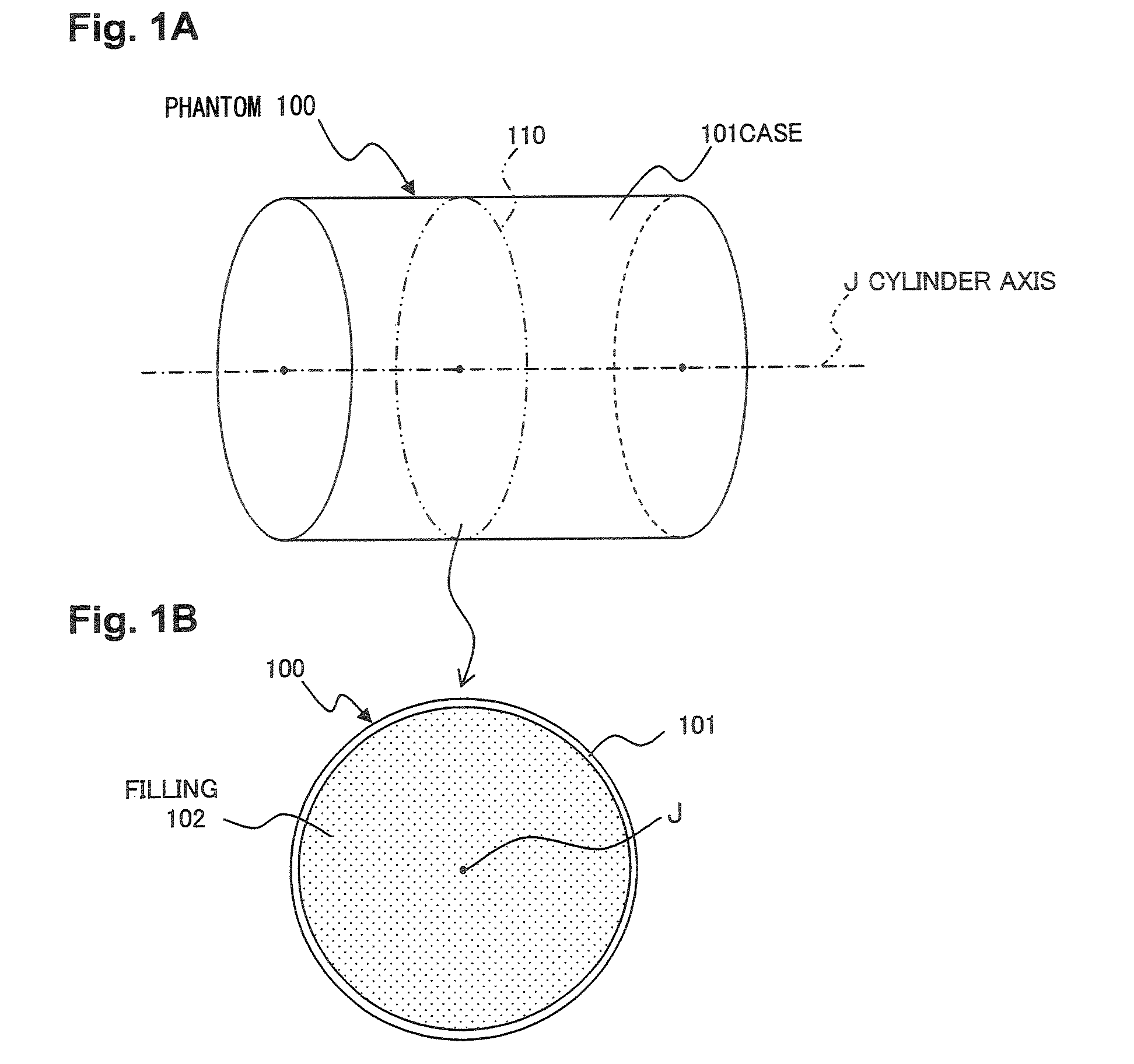
[0169]In the embodiment, it is possible to apply a composition to calculate a gradient direction of the phantom 100. A tomographic image of the phantom 100 is elliptical shape with the major axis in the gradient direction. For example, in the tomographic image 100B described in FIG. 7, Y-direction is the major axis, that means the phantom 100—tilts in the vertical direction.

[0170]Consequently, when a tomographic image with an elliptical shape is obtained, for example, by analyzing the image, the direction of the major axis is obtained (such as an angle relative to X-coordinate or Y-coordinate). The direction is the gradient direction of the phantom 100. As for the gradient direction, based on a radius in the gradient direction (a radius in the major axis direction) and a radius in the direction that intersects with the gradient direction at a right angle (a radius in the minor axis direction), it can be obtained in the same way as the equation in Equation 9. The obtained gradient di...


PUM


Abstract

The present invention comprises a top plate 31 for placing a cylindrical phantom 100, an X-ray tube 22 that generates X-rays, an X-ray detector 23 that detects X-rays transmitted through the phantom 100 placed on a top plate 31, a supporting body drive part 25 that rotates the X-ray tube 22 and X-ray detector 23, a tomographic image data generating part 60 that generates tomographic image data on the phantom 100 based on a results of detecting X-rays by the X-ray detector 23, a calculation processing part 80 that calculates displacement of the cylinder axis J of the phantom 100 relative to the center of rotation (center of scan) by the supporting body drive part 25, based on the tomographic image data, and the angle of gradient of the cylinder axis J relative to the normal direction (direction of slice) of the rotation plane of said rotation, and a monitor 5 that displays the calculated results.

Description

BACKGROUND OF THE INVENTION[0001]1. Field of the Invention[0002]The present invention relates to X-ray CT (computed tomography) apparatus, a method of aligning the phantom, and a phantom retaining tool, and more specifically relates to technology for aligning the phantom for X-ray CT apparatus.[0003]2. Description of the Related Art[0004]X-ray CT apparatus generates X-rays using an X-ray generator, and the X-rays that transmitted through an object on a bed are detected by an X-ray detector to form X-ray projection data, and it generates 2-dimensional tomographic image data showing the internal morphology of the object by applying a reconstruction processing to the X-ray projection data. Furthermore, with X-ray CT apparatus capable of a so-called helical scan, multiple tomographic image data can be reconstructed with a single scan by conducting a scan by rotation of an X-ray generator and an X-ray detector inside a gantry as the bed is being moved in the direction of the body axis (s...

Claims


Application Information

Patent Timeline
Patent Type & Authority Patents(United States)
IPC IPC(8): G01D18/00
CPCA61B6/541A61B6/583A61B6/581
Inventor SETO, HIROMITSU
Owner TOSHIBA MEDICAL SYST CORP
Why Eureka
Try Eureka