Roller chain sprocket

Inactive Publication Date: 2002-04-23
SANKYO OILLESS IND
View PDF6 Cites 17 Cited by
  • Summary
  • Abstract
  • Description
  • Claims
  • Application Information

AI Technical Summary

Problems solved by technology

This gap or backlash causes loss of movement when the transmission is made in reverse direction.
This non-theoretical tooth profile causes uncertainty of power transmission, and thus produces noise and vibration.
However, it leads to "undercut" of the profile, as described later, and p

Method used


Image

  • Roller chain sprocket
  • Roller chain sprocket
  • Roller chain sprocket

Examples


Embodiment Construction

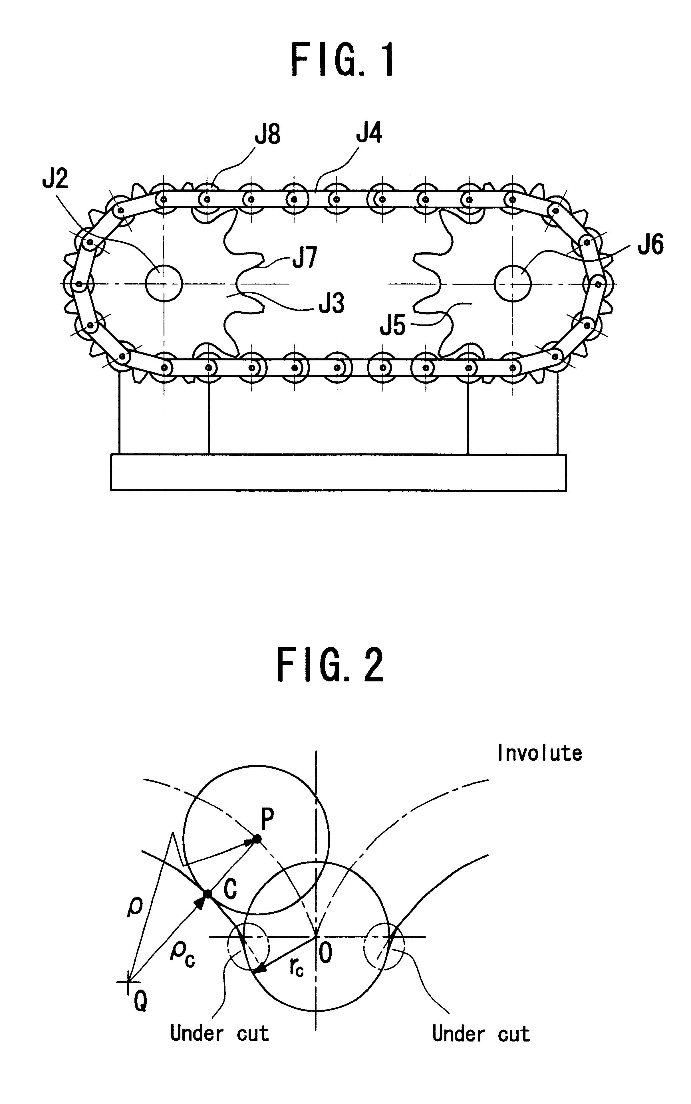
Referring to FIG. 1, a chain drive mechanism to which the present invention can be applied comprises two sprocket wheels J3 and J5 and a looped length of roller chain J4 moving round the opposite sprocket wheels J3 and J5. Each sprocket wheel J3 or J5 has a plurality of teeth J7 formed on its circumference, and an axle J2 or J6 integrally connected thereto to rotate as a whole. The chain J4 has a plurality of rollers J8 arranged at a constant pitch and rotatably connected thereto. The rollers J8 of the chain J4 can engage the teeth of the opposite sprocket wheels J3 and J5. In operation, the rotary movement is transmitted from the axle J2 to the sprocket wheel J3 at the input side of the chain drive mechanism, and then, the rotary movement is converted to the linear movement via engagement of the sprocket wheel J3 with the roller chain J4. The linear movement is converted to the rotary movement via engagement of the roller chain J4 with the sprocket wheel J5 at the output side, so t...


PUM


Abstract

An improved chain drive mechanism having a closed loop of roller chain passing round the opposite sprocket wheels. The profile of each tooth formed on the circumference of the sprocket wheel is in conformity with the envelope curve traced by a roller when the roller moves with its center following an involute-trochoid curve. The involute-trochoid curve is determined by offsetting the roller pitch line a certain distance apart outside the contact pitch line, and by rotating the contact pitch line on the base circle of the sprocket wheel to allow a point on the roller pitch line to trace a curve. The certain distance is so determined that the roller pitch may be equal to the incremental arc length, which is determined by dividing the circumference of the base circle by the number of teeth.

Description

1. Field of the InventionThe present invention relates to a chain drive mechanism which is capable of transmitting a rotary or linear movement to an associated mechanism via its chain.2. Prior ArtsSuch a rotary or linear movement transmission comprises two sprocket wheels each having a plurality of teeth formed on its circumference and being separated a given distance, and a length of chain passing round the opposite sprocket wheels.The profile of the sprocket tooth is defined in many national and international standards. These conventional design use a combination of several circular arcs and straight lines for the profile. For example, FIG. 8 shows a typical conventional design of the tooth profile, where the profile of the tooth C1 of the sprocket wheel is determined as the combination of two circular arcs R1 and R2. Sometimes a straight line is inserted between the two arcs (not shown). Each radius of the two arcs is bigger than the radius R4 of the roller C2. When in transmissi...

Claims


Application Information

Patent Timeline
IPC IPC(8): F16H55/02F16H55/30F16H7/00F16H7/06F16H19/06
CPCF16H55/30F16H7/06
Inventor MAKINO, HIROSHITERADA, HIDETSUGU
Owner SANKYO OILLESS IND
Why Eureka
Try Eureka