Cooling flow gas transition inserts in stator core ducts and methods of cooling a stator core

Inactive Publication Date: 2002-04-23
GENERAL ELECTRIC CO
View PDF7 Cites 10 Cited by
  • Summary
  • Abstract
  • Description
  • Claims
  • Application Information

AI Technical Summary

Benefits of technology

In accordance with a preferred embodiment of the present invention, there is provided a flow transition insert in each cooling duct that enables the flow path to gradually expand and thereby reduce the total pressure loss in the cooling ducts of the stator core. The radially extending cooling ducts which conduct cooling flow both radially inwardly and outwardly at different axial locations along the stator core include first and second radially extending cooling path sections. The first flow path section of each stator slot extends from the radially innermost portion of the core to the radially outermost portion of the armature bars and the second flow path section extends radially outwardly of the first flow path section. Thus, there is a juncture between the first and second flow path sections at the radially outermost portion of the armature bars. Where that juncture typically has an abrupt 90.degree. bend in current electrical machines, a transition insert is provided in the duct at the juncture of those sections and extends into the second flow path section to gradually transition the flow thereby reducing the pressure drop. The transition inserts per se may have linear or curvilinear surfaces in part defining the flow path. It will be appreciated that these surfaces permit the flow to expand or contract gradually and consequently reduce pressure losses at that juncture.
In a preferred embodiment according to the present invention, there is provided an electrical machine comprising a stator core including a plurality of axially spaced stator core laminations extending normal to an axis of the machine, armature bars passing generally axially through armature bar slots in the laminations, generally radially extending ducts defining flow paths for flowing a cooling gas through the stator core, the ducts extending between a pair of axially spaced laminations and about the axially extending armature bars, the armature bars forming with the ducts steps in the flow paths and defining first and second radially spaced flow path sections of the ducts, the first flow path sections extending generally radially alongside the armature bars and the second flow path section lying radially outward of the armature bars and the first flow path section and a gas flow transition element in each flow path radially outwardly of the armature bars having a flow surface for transitioning the flow along the duct between the first and second flow path sections thereof to minimize cooling gas flow losses associated with the step.
In a further preferred embodiment according to the present invention, there is provided in an electrical machine having a stator core including a plurality of stator core laminations, armature bars passing through armature slots in the laminations and through generally radially extending ducts defining flow paths for flowing a cooling gas through the stator core, the armature bars forming steps in the flow paths and defining first and second radially spaced flow path sections of the ducts, a method of cooling the stator core comprising the step of disposing a flow transition element in the second gas path section of each duct having a transition flow surface for gradually transitioning the flow between the first and second flow path sections to minimize cooling gas flow losses associated with said step.

Problems solved by technology

In certain electrical machines, the pressure drop through the stator core can become a limiting aspect of the overall machine cooling system.
These abrupt transitions cause pressure losses in addition to those occurring in the ducts when the cooling gas enters and exits the duct and as it flows along the duct.
All, however, entail a loss in total pressure.
Thus, a portion of system energy is irreversibly converted to heat and appears as a reduction in the efficiency of the overall machine.

Method used


Image

  • Cooling flow gas transition inserts in stator core ducts and methods of cooling a stator core
  • Cooling flow gas transition inserts in stator core ducts and methods of cooling a stator core
  • Cooling flow gas transition inserts in stator core ducts and methods of cooling a stator core

Examples


Embodiment Construction

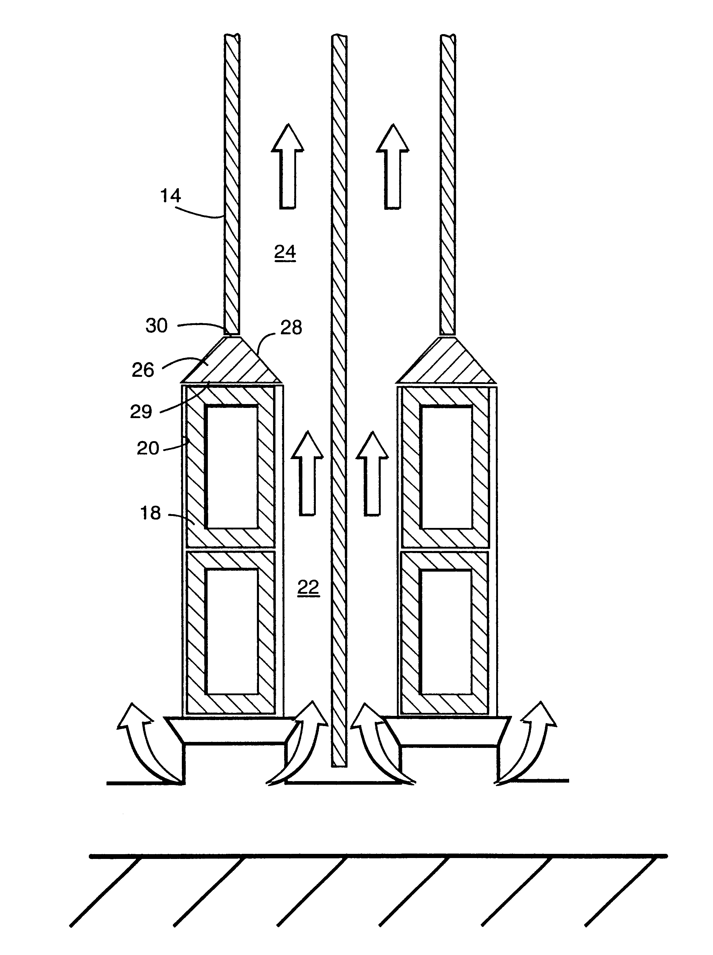
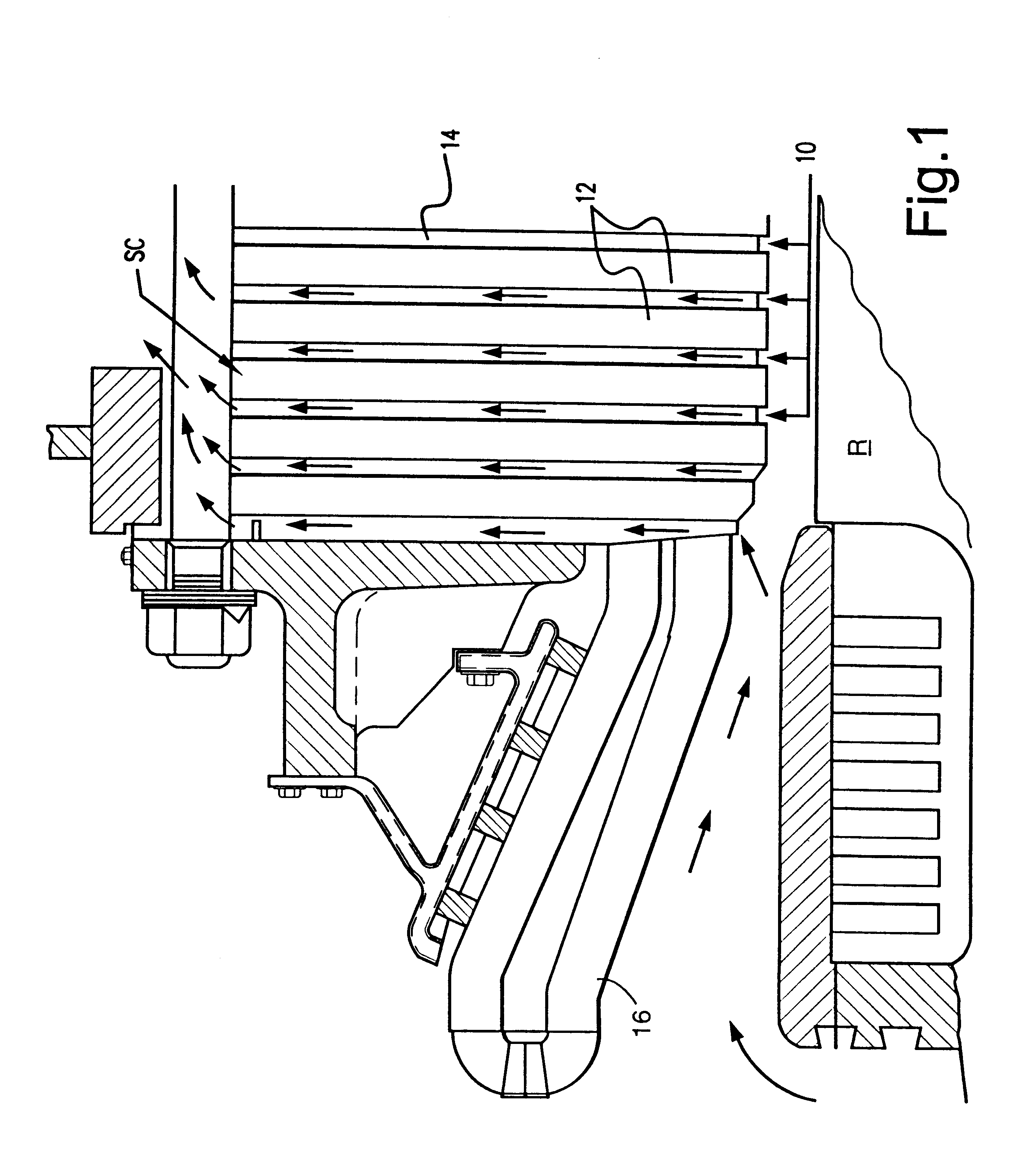
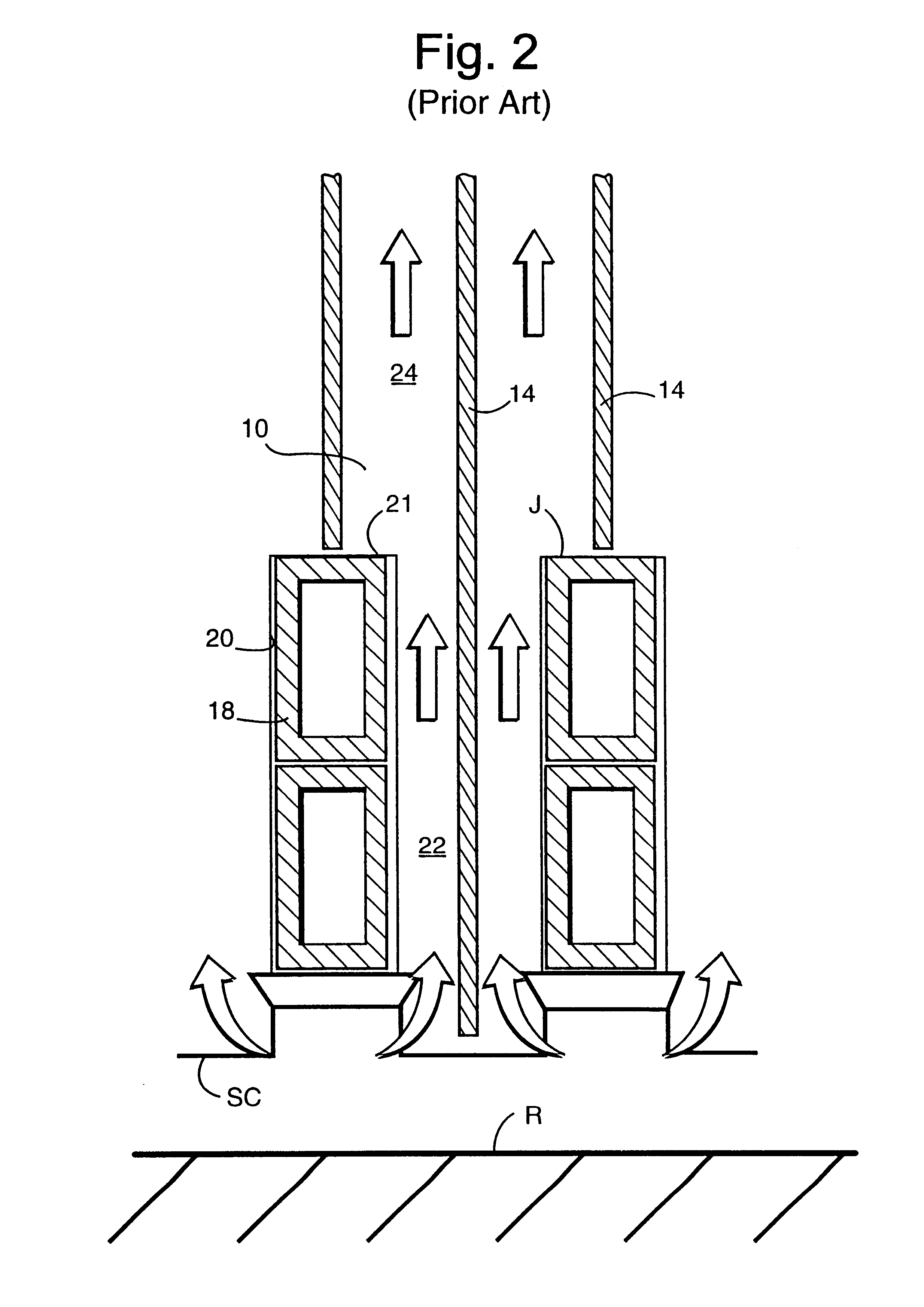
Referring now to the drawing figures, particularly to FIG. 1, there is illustrated an electrical machine comprised of a stator core SC having generally radially extending stacked layers of magnetic laminations 12. Ventilation ducts 10 are provided at axially spaced positions between groups or sets of laminations 12 and are defined in part by vent duct spacers 14 disposed between the respective groups or sets or laminations 12. Also illustrated in FIG. 1 is a portion of the rotor R and end windings 16 which form the ends of armature bars 18 passing axially through the stator core SC at circumferentially spaced positions in radially extending slots 20 (FIG. 2). The radial slots 20 extend along the inner portions of the stator core and are formed through the laminations 12. Thus, the armature bars 18 extend axially through the laminations, as well as the ducts 10. As illustrated in FIG. 2, the cooling gas in the illustrated form passes generally radially outwardly from between the roto...


PUM


Abstract

In electrical machines having a stator core formed by groups of stacked laminations spaced axially one from the other to define with spacers therebetween a plurality of radially extending cooling ducts, there is provided transition inserts in the flow passages. The inserts have surfaces which in part define the flow paths and form gradual transition surfaces between the flow path sections to minimize flow losses. The flow path surfaces of the transition inserts may be linear or curvilinear.

Description

BACKGROUND OF THE INVENTIONThe present invention relates to cooling flow transition inserts for transitioning gas flow in stator core cooling ducts of electrical machines and particularly relates to cooling flow transition inserts and methods of cooling the stator core which reduce the total pressure losses in the cooling ducts.In many electrical machines such as generators, particularly large-scale electrical machines, the stator cores must be cooled. It is a common practice to direct cooling gas for flow through a series of generally radially extending ducts that connect between the inner diameter of the stator core and its outer diameter. The ducts extend between sets or groups of laminations lying normal to the machine axis and at axially spaced locations along the stator core. In certain electrical machines, the pressure drop through the stator core can become a limiting aspect of the overall machine cooling system. This is particularly true in air-cooled machines in which air ...

Claims


Application Information

Patent Timeline
IPC IPC(8): H02K1/12H02K1/20H02K1/16
CPCH02K1/20H02K1/16
Inventor FOGARTY, JAMES MICHAEL
Owner GENERAL ELECTRIC CO
Why Eureka
Try Eureka