
Apparatus for detecting a synchronization signal in a digital data record/replay device

a technology of synchronization signal and digital data, applied in the field of analog data record/replay device, can solve problems such as signal degradation, interference with right signal detection, errors in sync pattern or data pattern,

Inactive Publication Date: 2002-04-23
LG ELECTRONICS INC
View PDF1 Cites 18 Cited by
  • Summary
  • Abstract
  • Description
  • Claims
  • Application Information

AI Technical Summary

Problems solved by technology

Damage in a tape, degradation of a signal, and an error in rotative velocity of a drum may interfere with right signal detection.
For example, there occur errors in the sync pattern or data pattern, or the number of clocks of a predetermined sync signal may not coincide with the number of clocks of an actual sync signal.
These signals may have irregular errors and this may cause the window signal to deviate from a substantial position.

Method used


Image

  • Apparatus for detecting a synchronization signal in a digital data record/replay device
  • Apparatus for detecting a synchronization signal in a digital data record/replay device
  • Apparatus for detecting a synchronization signal in a digital data record/replay device

Examples


Embodiment Construction

Reference will now be made in detail to the preferred embodiments of the present invention, examples of which are illustrated in the accompanying drawings.

Before undertaking the detailed description on an apparatus for detecting a sync signal in a digital data record / replay device according to the present invention, it may be advantageous to set forth concept and background of the present invention with reference to FIGS. 2 and 3.

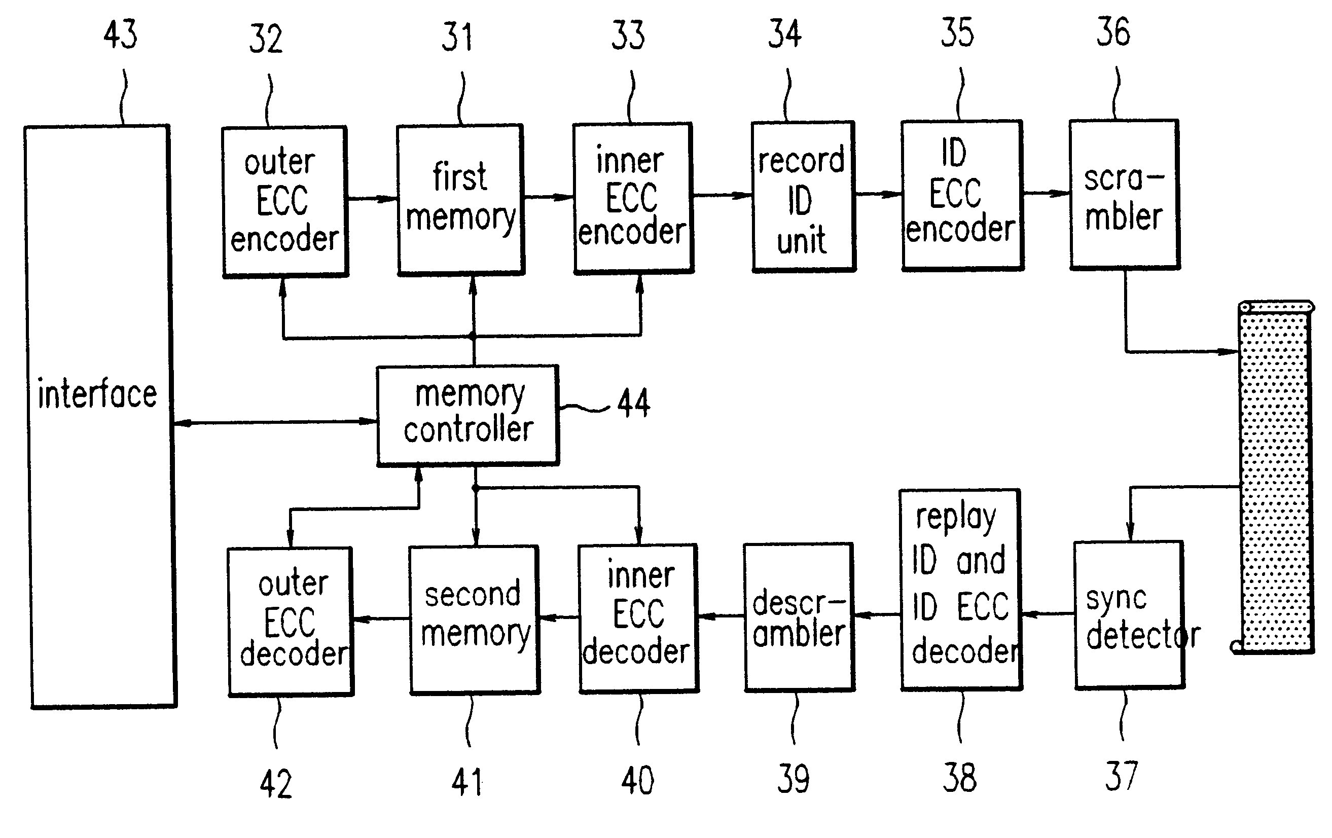
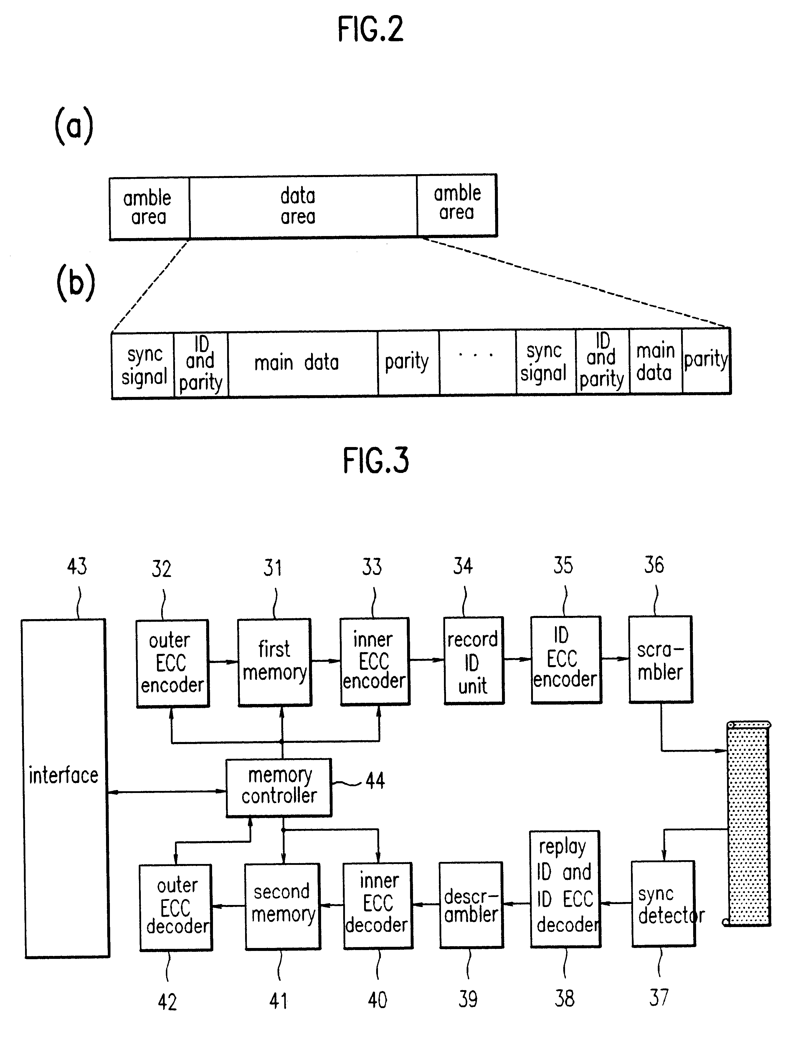
FIGS. 2(a) and 2(b) illustrate structure of a typical data track. FIG. 3 is a block diagram for explaining general idea of the apparatus for detecting a sync signal in a digital data record / replay device according to the present invention.

As shown in FIG. 2(a), The data track consists of amble areas and data areas. The data area, as shown in FIG. 2(b), consists of a plurality of sync signal areas, identification (ID) and parity areas, main data areas, and parity areas. Namely, the data area may be separated into several sync blocks.

As shown in FIG. 3, durin...


PUM

PropertyMeasurementUnit
rotative velocityaaaaaaaaaa
areaaaaaaaaaaa
widthaaaaaaaaaa

Abstract

An apparatus for detecting a sync signal in a digital data record / replay device having a parallel clock generator, a parallel data generator, and a window unit comprises: a sync signal detector for comparing a pattern matching sync signal output from a sync pattern detector with an output signal of the window unit and detecting a sync signal according to clocks of the parallel clock generator; a latch unit for latching the sync signal detected by the sync signal detector and outputting the sync signal as a sync position signal according to clocks of the parallel clock generator; an identification error correction code (ID ECC) controller for generating an ID ECC control signal according to the sync position signal of the latch unit; an ID ECC decoder for decoding ID areas of parallel data generated by the parallel data generator; and a sync signal checking unit for outputting the sync position signal of the latch unit as a final sync signal and, when errors are detected as a result of the ID ECC decoding, sending a control signal to the window unit. The present invention can check sync signals using the ID ECC and restore normal sync signals when an initial sync signal is erroneously detected due to unstableness of initial window signal or when sync signals are missed and erroneously detected due to change of clocks during the normal replay.

Description

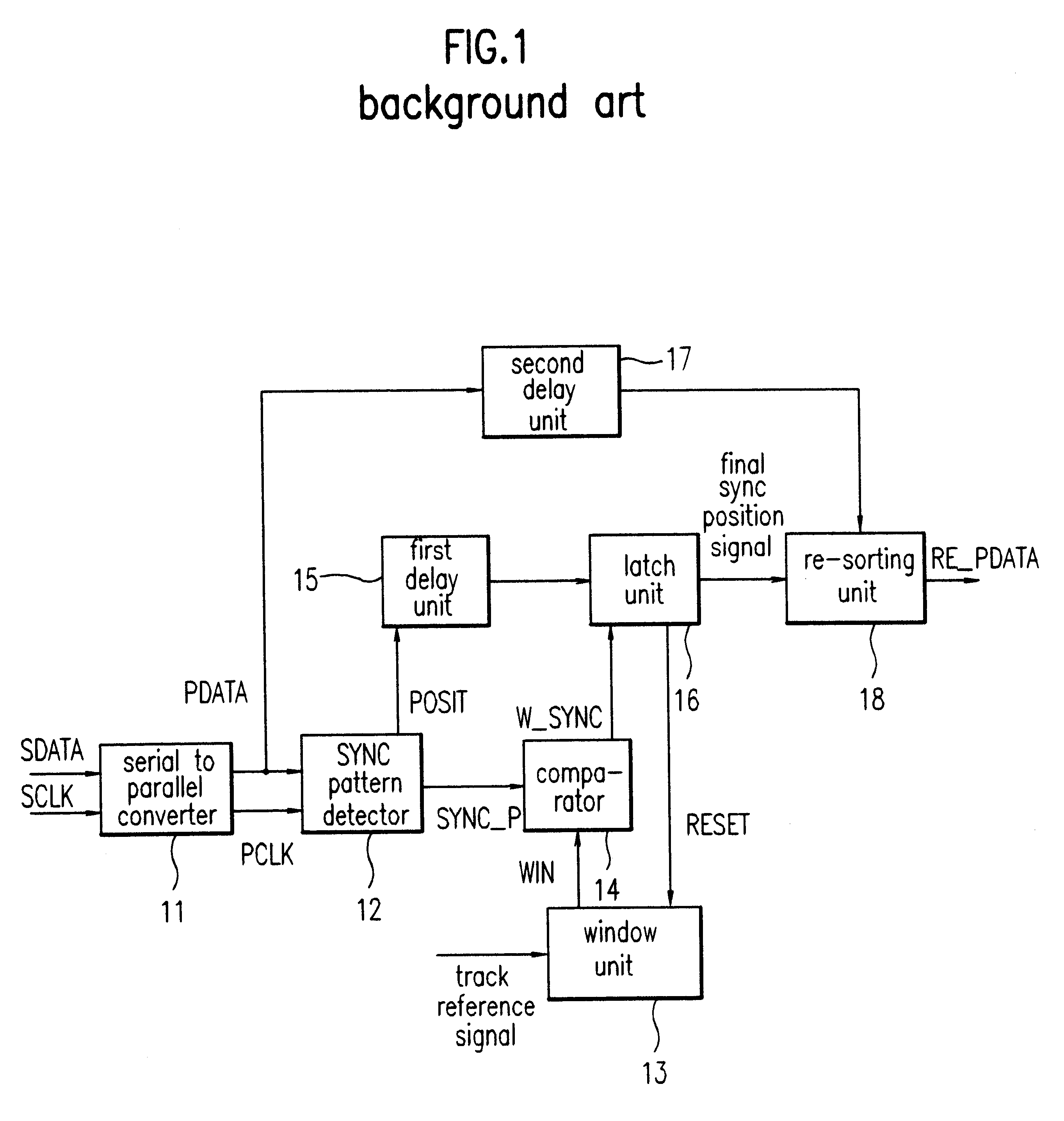
1. Field of the InventionThe present invention relates to a digital data record / replay device and more particularly to an apparatus for detecting a synchronization signal in a digital data record / replay device.2. Description of Related ArtTypically, erroneously detected sync signals are removed using a fixed window with respect to detected sync signals. At this time, if errors occur in data or a sync signal pattern or if the number of clocks of a predetermined sync signal does not coincide with the number of clocks of an actual sync signal, the detected sync signals may be all missed.FIG. 1 is a block diagram showing a configuration of a conventional apparatus for detecting a sync signal in a digital data record / replay device. The conventional apparatus includes: serial to parallel converter 11 for converting serial data, SDATA, and serial clocks, SCLK, which have been input as a result of reconstructing recorded data using an equalizer and phase locked loop (PPL), into parallel dat...

Claims


Application Information

Patent Timeline
Patent Type & Authority Patents(United States)
IPC IPC(8): G11B20/14G11B20/18G11B27/30H04L1/00H04L7/04G11B20/10
CPCG11B20/1426G11B20/1833G11B27/3027H04L7/042H04L1/004G11B20/10
Inventor LEE, DOO-HEEKWON, TAE-KYOUNG
Owner LG ELECTRONICS INC
Learn More