Fluorine-containing resin-coated pressure roller and heat-fixing device

a technology of fluorine-containing resin and pressure roller, which is applied in the direction of electrographic process apparatus, instruments, optics, etc., can solve the problems of paper dust attachment, paper wrinkles and paper winding around, and the surface of the roller is liable to be soiled,

Inactive Publication Date: 2002-04-23
CANON KK
View PDF31 Cites 60 Cited by
  • Summary
  • Abstract
  • Description
  • Claims
  • Application Information

AI Technical Summary

Problems solved by technology

However, in some cases of using a conventional pressure roller in such a film heating-type fixing device to operate the fixing device intermittently in a low temperature environment, the pressure roller surface is liable to be soiled with the toner to frequently result in difficulties, such as disorder of fixed images, paper wrinkles and paper winding about the pressure roller.
In a heat-fixing device of electricity economization-type having no standby temperature control means, the pressure roller surface is caused to contact transfer paper (recording material) before the surface is warmed, so that paper dust attachment is liable to occur.
However, if the pressure roller surface is not sufficiently heated, it is difficult to effect paper dust removal according to such mechanism.
Further, as mentioned above, in the film heating-type fixing device expected to perform electricity economization and shorter waiting time (i.e., improved quick-start characteristic), the heating member (fixing film) has a small heat capacity so that the pressure roller cannot be easily heated, and also in view of a demand for a smaller-size image forming apparatus, it is required to use a fixing film and a pressure roller of small diameters operated at a low pressure, so that it becomes difficult to obviate electrostatic offset.
Particularly during an intermittent operation in a low temperature environment, the amount of toner offset to the fixing film is liable to be increased.
However, in case where the pressure roller surface is not sufficiently heated, heat supply from the pressure roller is scarce and the toner is not sufficiently softened to generate a viscous adhesive force, so that a portion of the toner on the transfer paper can be electrostatically offset onto the fixing film surface.
The offset toner onto the fixing film can be transferred to and accumulated on the pressure roller, thus being liable to cause difficulties, such as fixed image disorder, paper wrinkles and paper winding about the pressure roller.
The conventional pressure rollers have been developed to have a lower hardness of the entire roller so as to ensure fixing and conveying performance, and have been unsatisfactory for obviating paper dust attachment onto the roller surface.
Further, many of the fixing devices developed heretofore are not equipped with a cleaning device therefor for the propose of cost reduction, etc.
Further, the use of smaller particle size toner for providing higher quality images in recent years makes difficult the cleaning by such cleaning means and has promoted the paper dust attachment.
Such a filler is however liable to be attached onto the pressure roller, the fixing roller or fixing film, etc., thereby lowering the releasability of these members, so that the toner is liable to be accumulated on the pressure roller to result in spotty defects in the resultant images, and a difficulty such as paper winding about the pressure roller, leading to paper jamming, is liable to be caused.
On the other hand, if the pressure roller surface has a micro-rubber hardness exceeding 50 deg., it becomes difficult to attain the above effect due to insufficient circumferential elongation and contraction of the pressure roller surface at and in the neighborhood of the nip.

Method used


Image

  • Fluorine-containing resin-coated pressure roller and heat-fixing device
  • Fluorine-containing resin-coated pressure roller and heat-fixing device
  • Fluorine-containing resin-coated pressure roller and heat-fixing device

Examples


example 1

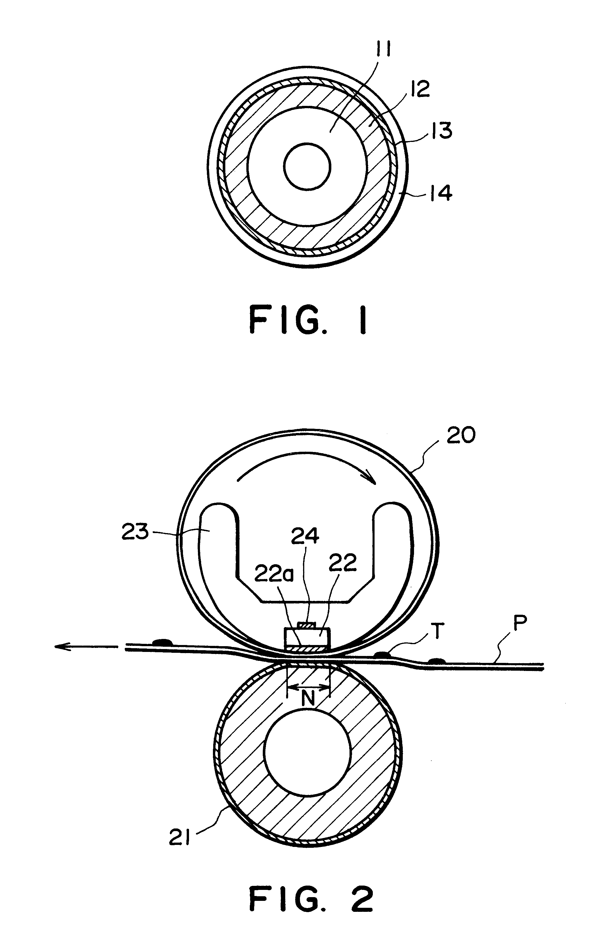
Four pressure rollers (Examples 1-1 to 1-4) each having a structure as shown in FIG. 1 were prepared as follows.

A 2 mm-thick aluminum core cylinder was coated with an elastic layer of silicone rubber ("DY35-561A / B", mfd. by Toray Dow Corning Silicone K.K.) in a thickness of 2.5 mm, a length of 225 mm and an outer diameter of 20 mm). After being treated with a primer, the coated cylinder was further coated successively with an adhesive layer of a fluorine-containing rubber / fluorine-containing resin mixture and a release layer of fluorine-containing resin having thicknesses shown at Examples 1-1 to 1-4 in Table 1 appearing hereinafter. Each adhesive layer was formed by application of a solution in methyl isobutyl ketone of the following formulation A, followed by drying and curing. The formulation A after curing exhibited a hardness of 90 deg.

Formulation A

The surface release layer was formed by application of an FEP dispersion liquid ("ND1", mfd. by Daikin Kogyo K.K.) followed by dryi...

example 2

Two pressure rollers (Examples 2-1 and 2-2) were prepared in a similar manner as in Example 1.

More specifically, an aluminum cylinder coated with a silicone rubber layer and a primer similarly as in Example 1 was further coated with an adhesive layer (of a fluorine-containing rubber / fluorine-containing resin mixture) and a release layer of fluorine-containing resin having thickness (at Example 2-1 or Example 2-2) in Table 2. The adhesive layers in Examples 2-1 and 2-2 were formed by application of solutions of the following formulations B and C, respectively, followed by drying and curing. After curing, the adhesive layers exhibited JIS-A rubber hardness of 73 deg. and 70 deg., respectively.

Formulation B

Formulation C

For each pressure roller, the surface layer was formed by applying a PFA dispersion liquid ("AD-2", mfd. by Daikin Kogyo K.K.), followed by drying, baking and a surface-smoothing treatment at 300.degree. C. for 3 min. otherwise in the same manner as in Example 1. The sur...

example 3

Though Example 3 and Comparative Examples 2 and 3 were described above as representative, but other pressure rollers were also prepared by using various thicknesses of adhesive layers and surface release layers and degrees of surface-smoothing treatments. The results of performance evaluation in the above-described manner are summarized in FIGS. 5 and 6. More specifically, FIG. 5 shows the performance evaluation results on a graph with an abscissa of roller surface hardness and an ordinate of contact angle with water. In FIG. 5, each spot .smallcircle. represents that toner soiling did not occur until 5000 sheets, each spot .DELTA. represents that toner soiling occurred at 3000 sheets, and each spot X represent that toner soiling occurred even at an initial stage. As is understood from FIG. 5, toner soiling prevention characteristic is inferior at a contact angle of ca. 105 deg. or below. However, even at a contact angle of 105 deg. or higher, the toner soiling prevention characteri...


PUM


Abstract

A fluorine-containing resin-coated pressure roller exhibiting excellent anti-toner soiling characteristic even at low roller temperatures is provided. The pressure roller includes a cylindrical metal substrate, and a rubber elastic layer, an adhesive layer and a fluorine-containing resin release layer disposed in this order on and successively coating the cylindrical metal substrate. The pressure roller has a surface exhibiting a micro-rubber hardness of at most 50 deg., a contact angle with water of at least 105 deg. and a ten point-average surface roughness Rz of at most 3.0 mum. The pressure roller may be suitably combined with a fixing film to provide a film heating-type fixing device suitably used in an electrophotographic image forming apparatus.

Description

FIELD OF THE INVENTION AND RELATED ARTThe present invention relates to a pressure roller and a heat-fixing device including such a pressure roller for use in an electrophotographic image forming apparatus. More specifically, the present invention relates to a roller for nipping a recording material for conveying the recording material, and particularly a pressure roller used in a heat-fixing device for permanently fixing a toner image onto a recording material in a recording system according to, e.g., electrophotography or electrostatic recording.Many of conventional electrophotographic copying machines and printers have adopted, as fixing means, those of the heat-fixing type including a contact-heating hot roller fixing device exhibiting good heat efficiency and safeness and a film-heating type fixing devices requiring less energy consumption.A heat-fixing device of the hot roller type includes a heating roller (fixing roller) as a rotating member for heating and an elastic pressur...

Claims


Application Information

Patent Timeline
Patent Type & Authority Patents(United States)
IPC IPC(8): G03G15/20
CPCG03G15/2053G03G15/206G03G2215/2035
Inventor KISHINO, KAZUOOHTSUKA, YASUMASAOCHIAI, TOSHIHIKOTAKAHASHI, MASAAKIHAYAKAWA, AKIRAKAWAMOTO, HIDEOYOSHIOKA, MAHITOSOUTOME, OSAMUKARASHIMA, KENJIKITANO, YUJI
Owner CANON KK
Why Eureka
Try Eureka