
Centrifuge permeameter for unsaturated soils system

a centrifuge and soil technology, applied in the field of permeameters, can solve the problems of inefficient resource use, inability to directly acquire relevant variables, and inability to determine the fluid retention curve and hydraulic conductivity function simultaneously,

Inactive Publication Date: 2007-06-14
BOARD OF RGT THE UNIV OF TEXAS SYST
View PDF8 Cites 12 Cited by
  • Summary
  • Abstract
  • Description
  • Claims
  • Application Information

AI Technical Summary

Benefits of technology

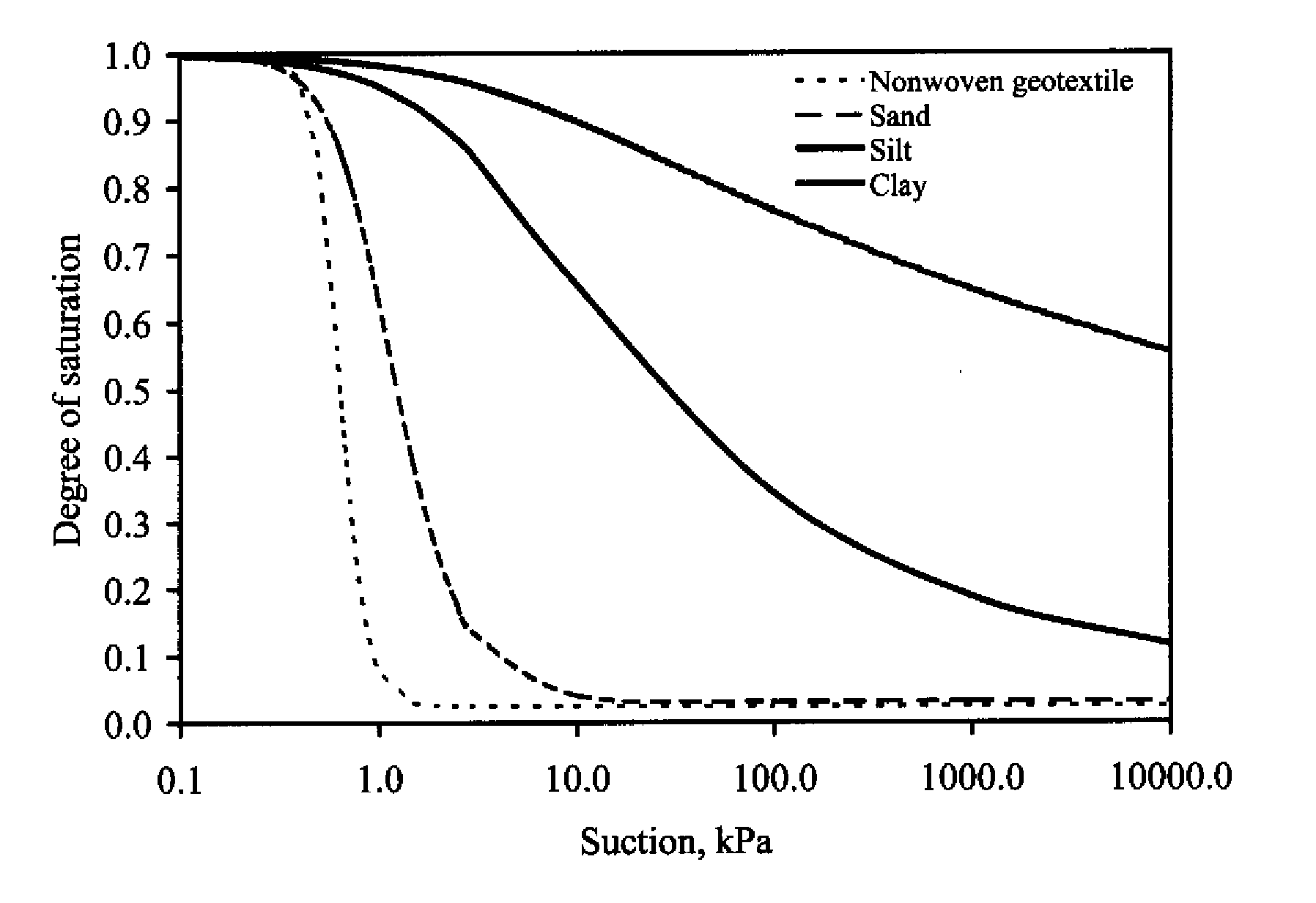
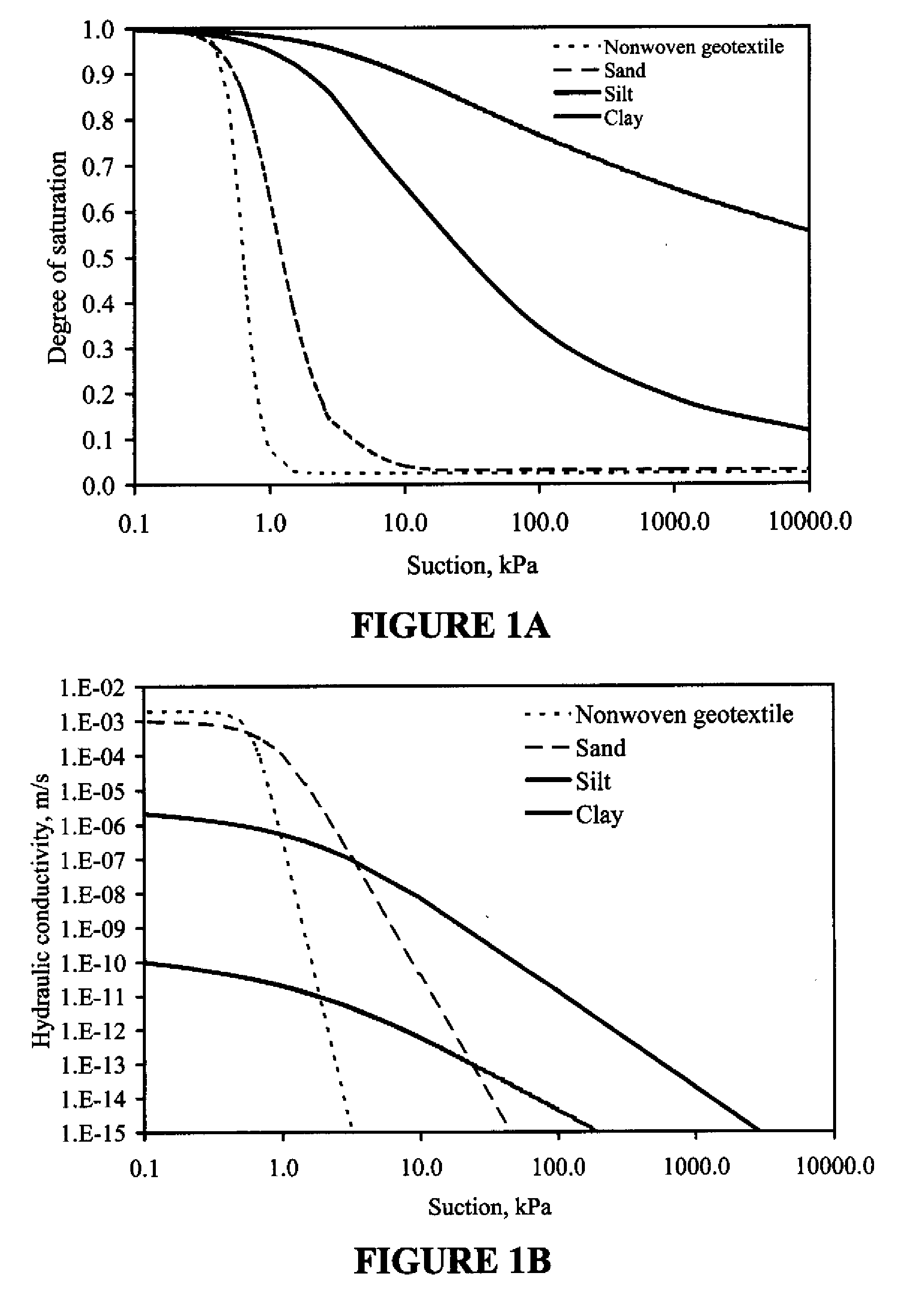
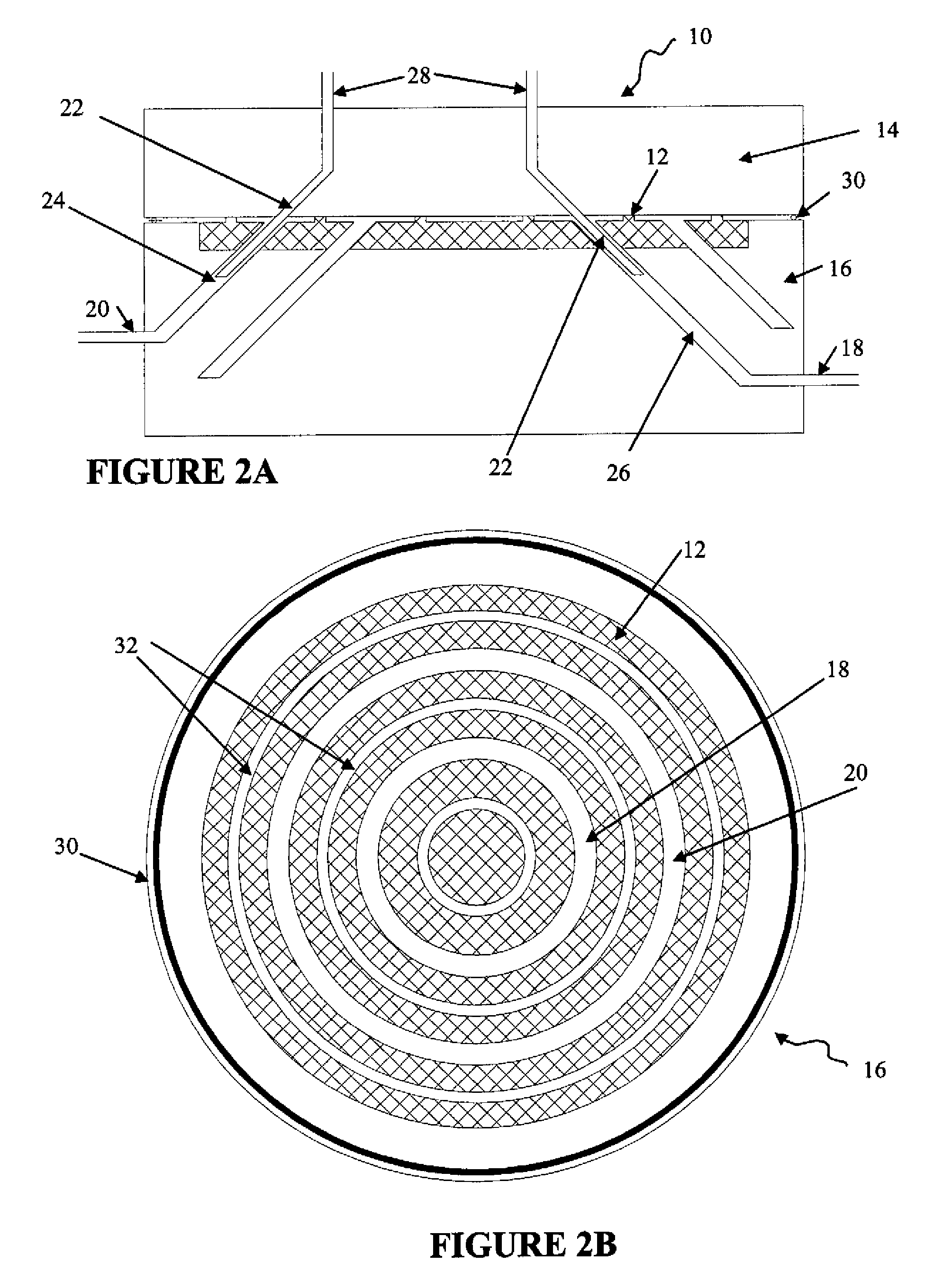
The present invention is an apparatus, method, and system for a centrifuge permeameter that allows for continuous, non-destructive, and non-intrusive measurement of relevant hydraulic variables in a single specimen during centrifugation. The permeameter controls the inflow and outflow boundary conditions to generate open-flow boundary conditions that do not interfere with the ongoing flow process. The apparatus can measure one or more variables such as suction, moisture content, hydraulic conductivity, and the relationship between them. The invention allows for the simultaneous determination of the fluid retention curve and hydraulic conductivity function, which was previously only achievable with several specimens and time-consuming testing. The permeameter system can be used in various fields such as soil, rock, and concrete engineering. The invention also includes a method for measuring unsaturated soil characteristics by placing a soil sample in the centrifuge permeameter and measuring the one or more characteristics while in flight. The permeameter is designed to control the inflow and outflow boundary conditions to generate open-flow boundary conditions that do not interfere with the ongoing flow process. The invention allows for the continuous, non-destructive, and non-intrusive measurement of relevant hydraulic variables in a single specimen during centrifugation.

Problems solved by technology

Furthermore, it was found that available technologies do not allow determination of the fluid retention curve and hydraulic conductivity function simultaneously.
Also, current centrifuge technology does not allow the direct acquisition of the relevant variables (e.g., suction, moisture content, fluid flow rate) in-flight during testing.
The time-consuming nature of current conventional technology and its effect on test data, results in inefficient use of resources and limited usefulness for the data gathered.
Overall, the apparatus, system and method may be used for low-hydraulic conductivity materials, the hydraulic properties of which cannot be obtained in a practical manner using currently available technology.

Method used


Image

  • Centrifuge permeameter for unsaturated soils system
  • Centrifuge permeameter for unsaturated soils system
  • Centrifuge permeameter for unsaturated soils system

Examples


Embodiment Construction

[0028] While the making and using of various embodiments of the present invention are discussed in detail below, it should be appreciated that the present invention provides many applicable inventive concepts that can be embodied in a wide variety of specific contexts. The specific embodiments discussed herein are merely illustrative of specific ways to make and use the invention and do not delimit the scope of the invention.

[0029] To facilitate the understanding of this invention, a number of terms are defined below. Terms defined herein have meanings as commonly understood by a person of ordinary skill in the areas relevant to the present invention. Terms such as “a”, “an” and “the” are not intended to refer to only a singular entity, but include the general class of which a specific example may be used for illustration. The terminology herein is used to describe specific embodiments of the invention, but their usage does not delimit the invention, except as outlined in the claim...


PUM

PropertyMeasurementUnit
flow ratesaaaaaaaaaa
flow rateaaaaaaaaaa
flow rateaaaaaaaaaa

Abstract

The present invention includes an apparatus, method and centrifuge permeameter system that includes a hydraulic permeameter adapted for use in a centrifuge; and an automated data acquisition system, wherein the centrifuge permeameter non-destructively determines one or more soil characteristics from a sample of granular material such as soil, rock, and concrete when centrifuged.

Description

CROSS-REFERENCE TO RELATED APPLICATIONS [0001] This application claims priority to U.S. Provisional Application Ser. No. 60 / 634,189, filed Dec. 8, 2004, the contents of which are incorporated by reference herein in their entireties.BACKGROUND OF THE INVENTION [0002] This invention was made with U.S. Government support under Contract No. CMS-0094007 awarded by the NSF. The government may own certain rights in this invention. Without limiting the scope of the invention, its background is described in connection with soil permeameters.TECHNICAL FIELD OF THE INVENTION [0003] The present invention relates in general to the field of permeameters, and more particularly, to a centrifuge permeameter that allows continuous, non-destructive and non-intrusive measurements of relevant variables. [0004] For example, U.S. Pat. No. 4,679,422, issues to Rubin, et al., discloses a method and apparatus for steady-state measurement of liquid conductivity in porous media. U.S. Pat. No. 6,634,876, issued...

Claims


Application Information

Patent Timeline
Patent Type & Authority Applications(United States)
IPC IPC(8): G01N15/08G01N33/24G01N1/18G01N1/44
CPCG01N15/08G01N15/0826Y10T436/25375G01N2033/245G01N33/246G01N33/245
Inventor ZORNBERG, JORGE G.MCCARTNEY, JOHN S.
Owner BOARD OF RGT THE UNIV OF TEXAS SYST
Learn More