This helps you quickly interpret patents by identifying the three key elements:
Problems solved by technology
Method used
Benefits of technology
Problems solved by technology
When the response of the actuator to the lever operation is excessively sensitive, there involves inconveniences such that when in operation, the actuator is actuated with the shock; it is difficult to hold the lever operating amount constant; or when the lever operation is changed in slight amount, the actuator sensitively reacts therewith to bring forth hunting.
It is difficult for an unskilled operator to handle such a sensitively operating actuator as described.
Method used
Image
Click on the blue label to locate the original text in one second.
Reading with bidirectional positioning of images and text.
Examples
first embodiment
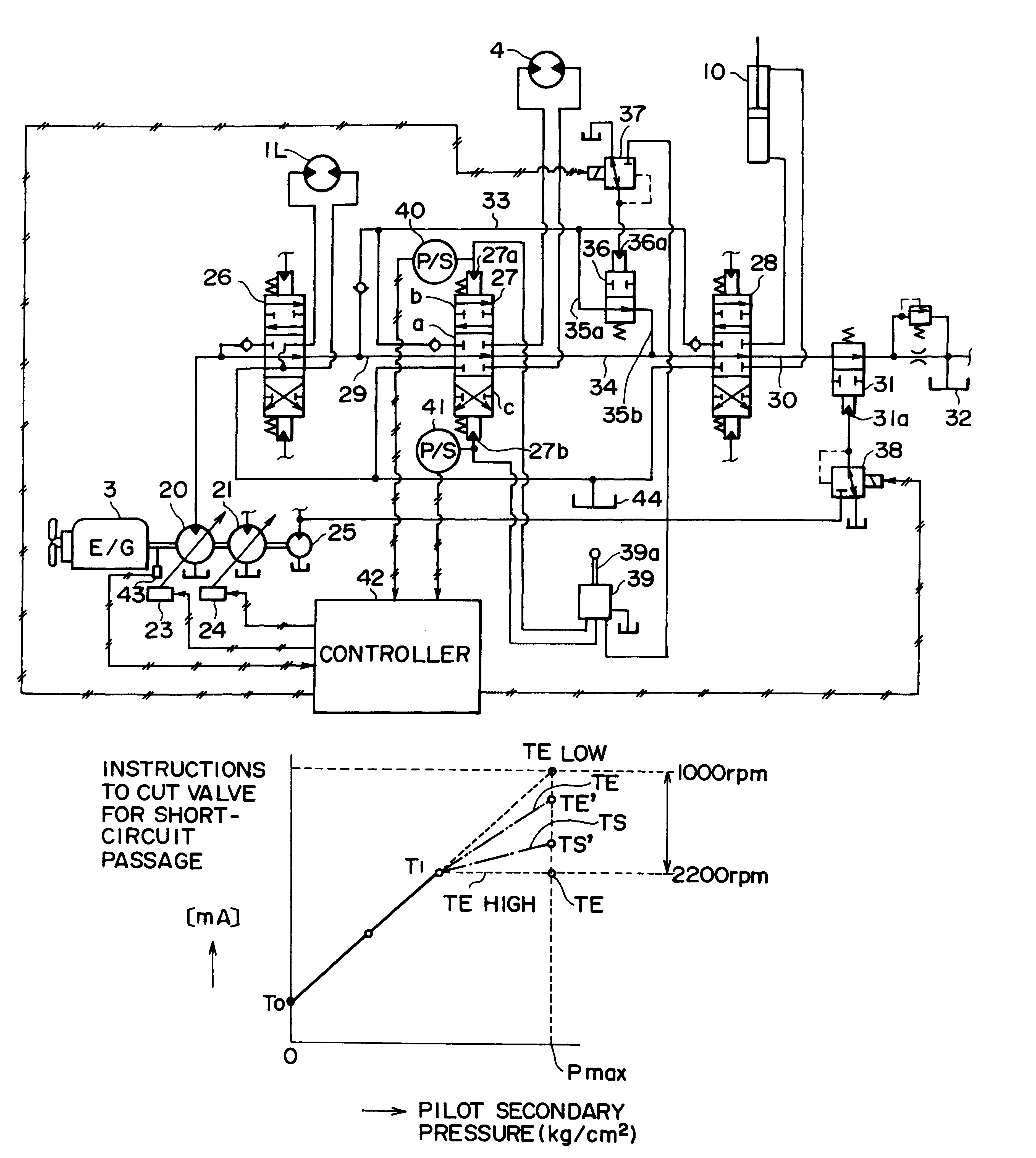
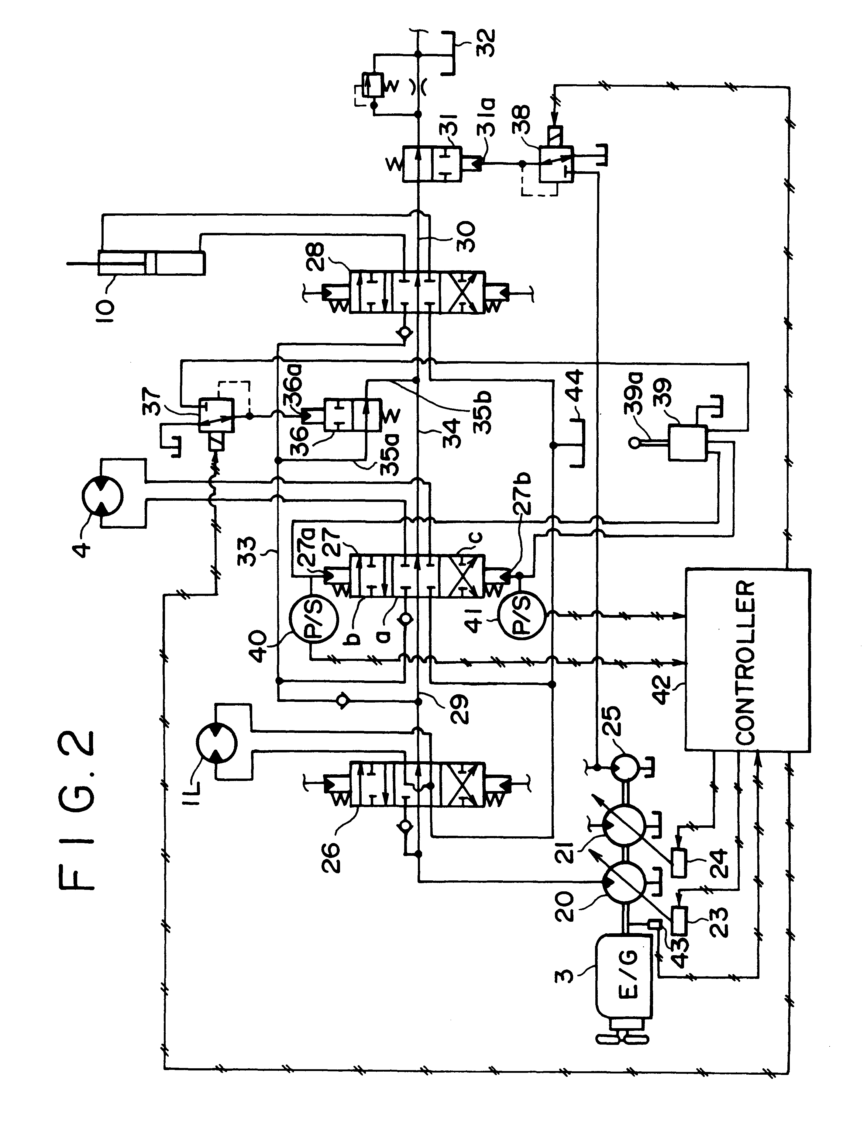
FIGS. 2 to 4 show a hydraulic control device provided on the hydraulic excavator shown in FIG. 1. In FIG. 2, reference numerals 20, 21 denote first and second hydraulic pumps for discharging main pressure oil driven by the engine 3, and 23, 24 denote regulators for adjusting a slant-plate tilting amount of the hydraulic pumps 20, 21.
Reference numeral 25 denotes a pilot pump; 26 a control valve for travel for controlling the travel motor 1L; 27 a control valve for swing (a control valve connected to a specific actuator) for controlling the swing motor (a specific actuator) 4; 28 a control valve for arm for controlling the arm cylinder 10; and 29 a center bypass oil path for flowing pressure oil from the first hydraulic pump 20 passing through neutral positions of the control valves 26, 27 and 28, respectively.
Reference numeral 30 denotes an outlet side flowpassage of the center bypass oil path 29; and 31 a cut valve for return oil provided in the outlet side flowpassage 30 to pass or...
second embodiment
FIG. 5 shows the hydraulic control device according to the present invention. In the following drawing, the same constituent elements as those shown in FIG. 2 are indicated by the same reference numerals, description of which will be omitted. For simplifying the description, a circuit for singly operating a swing motor is shown.
In FIG. 5, the pressure oil discharged from the first hydraulic pump 20 flows into the working oil tank T through the center bypass line 50, and to the center bypass line 50 are connected the control valve for travel 26, the control valve for arm 28, and the control valve for swing (a control valve connected to a specific actuator) 51.
The control valve for arm 28 is connected in tandem to the downstream of the control valve for travel 26, and the control valve for arm 28 and the control valve for swing 51 are connected in parallel through a pipe line 52.
The control valve for swing 51 has three passages, i.e., a meter-in, a meter-out, and a bleed-off (in a neu...
third embodiment
FIG. 8 shows the hydraulic control device according to the present invention.
In the hydraulic circuit shown in FIG. 8, a control valve for swing 58 is provided with passages for a meter-in, a meter-out and a bleed off, but this circuit is different from the circuit constitution shown in FIG. 5 in that the control of the bleed off flow rate is exclusively carried out by the cut valve 54.
In case of this constitution, the controller 57 selects the cut valve control pilot pressure pattern shown in FIG. 6 according to the engine rotational frequency detected by the rotational frequency sensor 43 and control the cut valve 54 in accordance with the selected pattern, but since a throttle is not provided on the bleed off passage of the control valve for swing (a control valve connected to a specific actuator) 58, the control of the bleed off flow rate is to be carried out by the single operation of the cut valve 54.
If an arrangement is made such that the bleed off flow rate is controlled by ...
PUM
Abstract
A hydraulic control apparatus for a working machine in which a flow rate and a direction of pressure oil discharged from a hydraulic pump are controlled by a control valve to supply it to a swing motor, comprising: a bleed-off oil path for bleeding off a part of the pressure oil supplied to the swing motor, a cut valve provided on the bleed-off oil path to adjust a bleed-off amount, a controller for controlling the cut valve through a solenoid proportional valve, and pressure sensors for detecting an operating amount of a remote control valve for swing, characterized in that the controller sets the bleed-off amount according to the operating amount detected by the pressure sensors, controls an opening area of the cut valve on the basis of the bleed-off amount set, and suppresses the shock when sudden swinging operation takes place.
Description
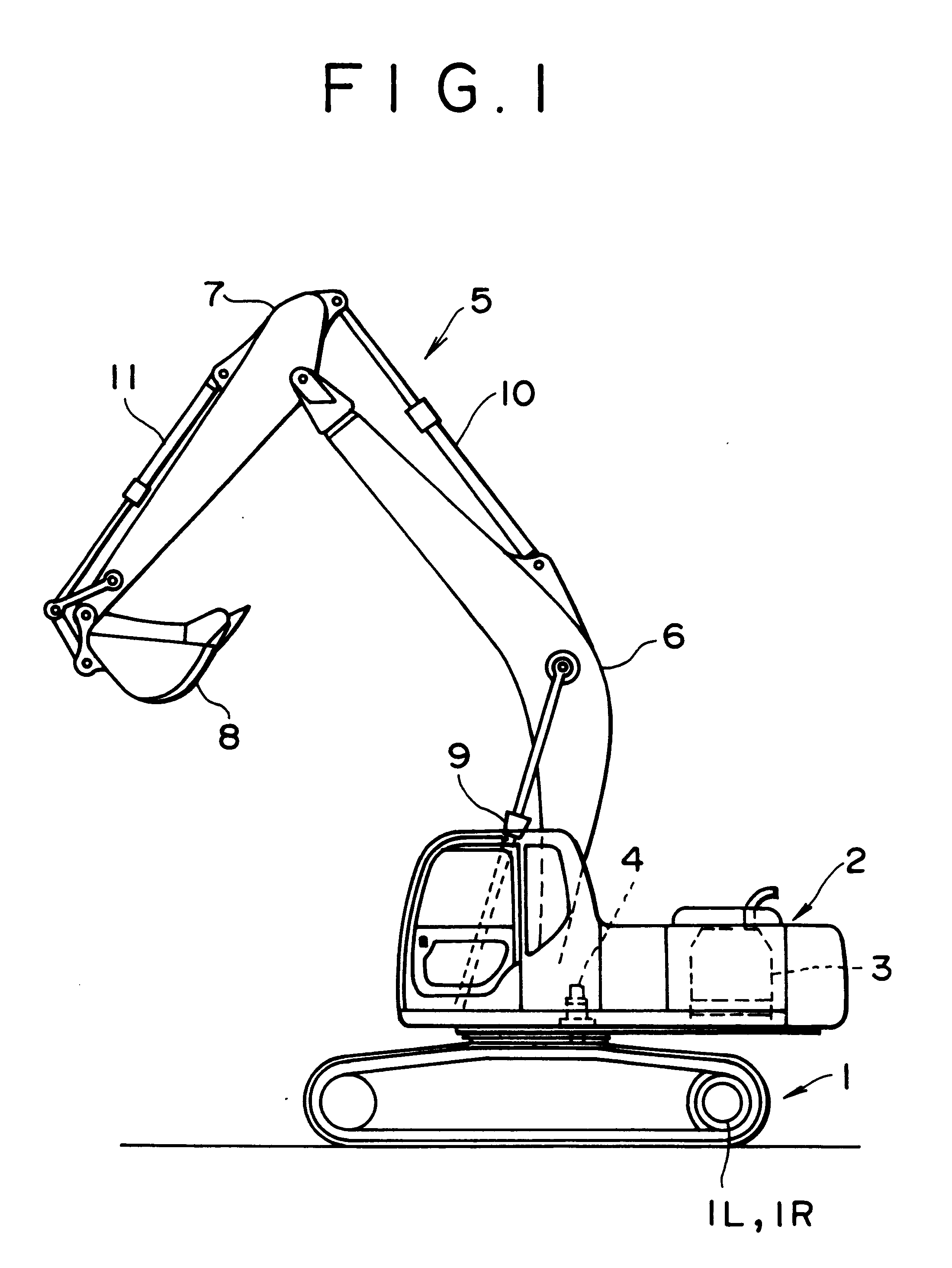
1. Field of the InventionThe present invention relates to a hydraulic control device of controlling an actuator provided on a working machine such as a hydraulic excavator, and particularly to a hydraulic control device of a working machine suitable for controlling a swinging operation.2. Description of the Related ArtConventionally, in the hydraulic excavator as the working machine, when attachments such as a swing motor, a travel motor, a boom cylinder, an arm cylinder, a bucket cylinder and so on are operated, an operating lever is operated to a full lever at a stretch, a lever operating amount is held constant, or the operating amount is somewhat changed while operating the actuator in a constant amount.When the response of the actuator to the lever operation is excessively sensitive, there involves inconveniences such that when in operation, the actuator is actuated with the shock; it is difficult to hold the lever operating amount constant; or when the lever operation is chang...
Claims
Application Information
Patent Timeline
Application Date:The date an application was filed.
Publication Date:The date a patent or application was officially published.
First Publication Date:The earliest publication date of a patent with the same application number.
Issue Date:Publication date of the patent grant document.
PCT Entry Date:The Entry date of PCT National Phase.
Estimated Expiry Date:The statutory expiry date of a patent right according to the Patent Law, and it is the longest term of protection that the patent right can achieve without the termination of the patent right due to other reasons(Term extension factor has been taken into account ).
Invalid Date:Actual expiry date is based on effective date or publication date of legal transaction data of invalid patent.

