Clutch device with a hydrodynamic clutch and at least two friction clutches

a technology of hydrodynamic clutch and friction clutch, which is applied in the direction of rotary clutches, fluid couplings, couplings, etc., can solve the problems of increased wear of friction clutches, and heat must be carried away

Inactive Publication Date: 2002-04-30
ZF FRIEDRICHSHAFEN AG
View PDF34 Cites 44 Cited by
  • Summary
  • Abstract
  • Description
  • Claims
  • Application Information

AI Technical Summary

Problems solved by technology

This results in high slippage which brings about extensive development of heat.
Consequently, not only is there the problem that this heat must be carried away from the area of extension of the friction clutch, but increased wear of the friction clutches must also be taken into account.
Further, heating of this kind leads to changes in the coefficient of friction at the friction clutches so that the control of the two release mechanisms, and therefore of the two friction clutches relative to one another, can be appreciably impaired.
This is incompatible with a problem-free torque transmission in shifting processes in the shift transmission without interruption of tractive force and without jerking during shifting.
Specifically, as a result of inaccuracies in functional matching of the two friction clutches relative to one another caused by heat, a torque ratio not intended in the shifting process is applied to the two transmission input shafts, which can lead to shifting processes in the shift transmission under load.
This can overtax the synchronization in the shift transmission so that, aside from the disadvantages with respect to efficiency, the shift transmission can be damaged to the point of complete failure.
Also problematic in clutch devices of this kind are starting processes which are either carried out in opposition to an inclination, wherein the motor vehicle must be prevented from rolling backward, or which are used when parking at the lowest possible speed for precise positioning of the motor vehicle in a parking space.
Although the torques to be transmitted in such starting processes lie well below those in the operating condition described above, an intensive heating of the friction clutches can occur, resulting in the problems detailed above.
The risk of intensive overheating exists not only in a dry friction clutch, but can also occur in so-called "wet" friction clutches, preferably in the form of a disk or plate clutch which is arranged within a viscous medium such as hydraulic fluid.
However, in spite of the liquid cooling, heating of the friction clutches constitutes a considerable problem because, on the one hand, the viscous medium overheats when flowing through flow passages in the form of channels usually provided in friction surfaces of the friction clutch and can accordingly be destroyed and, on the other hand, due to the building up of an opposing pressure between the friction surfaces of two adjacent plates with intensive flow through these grooves, capacity of the friction clutch to transmit torque is reduced and the problem of overheating is therefore exacerbated due to increased slippage.
Particularly in plate clutches, this problem can result in that the friction surfaces can no longer separate from one another completely after a disengaging process and, consequently, considerable drag torques can sometimes reach the shift transmission because one of the friction clutches is already closed, while the other has not yet completely opened.

Method used


Image

  • Clutch device with a hydrodynamic clutch and at least two friction clutches
  • Clutch device with a hydrodynamic clutch and at least two friction clutches
  • Clutch device with a hydrodynamic clutch and at least two friction clutches

Examples


Embodiment Construction

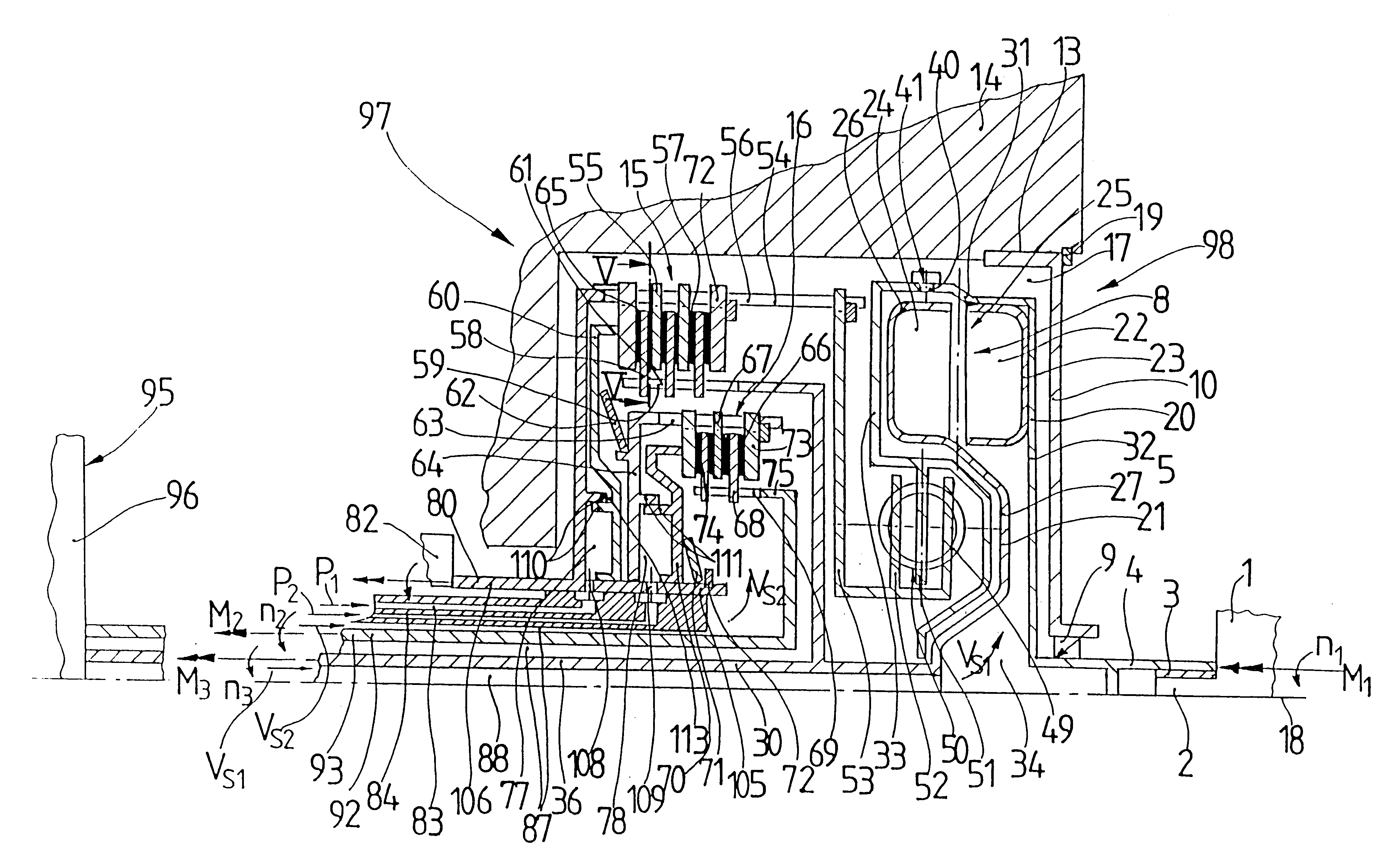
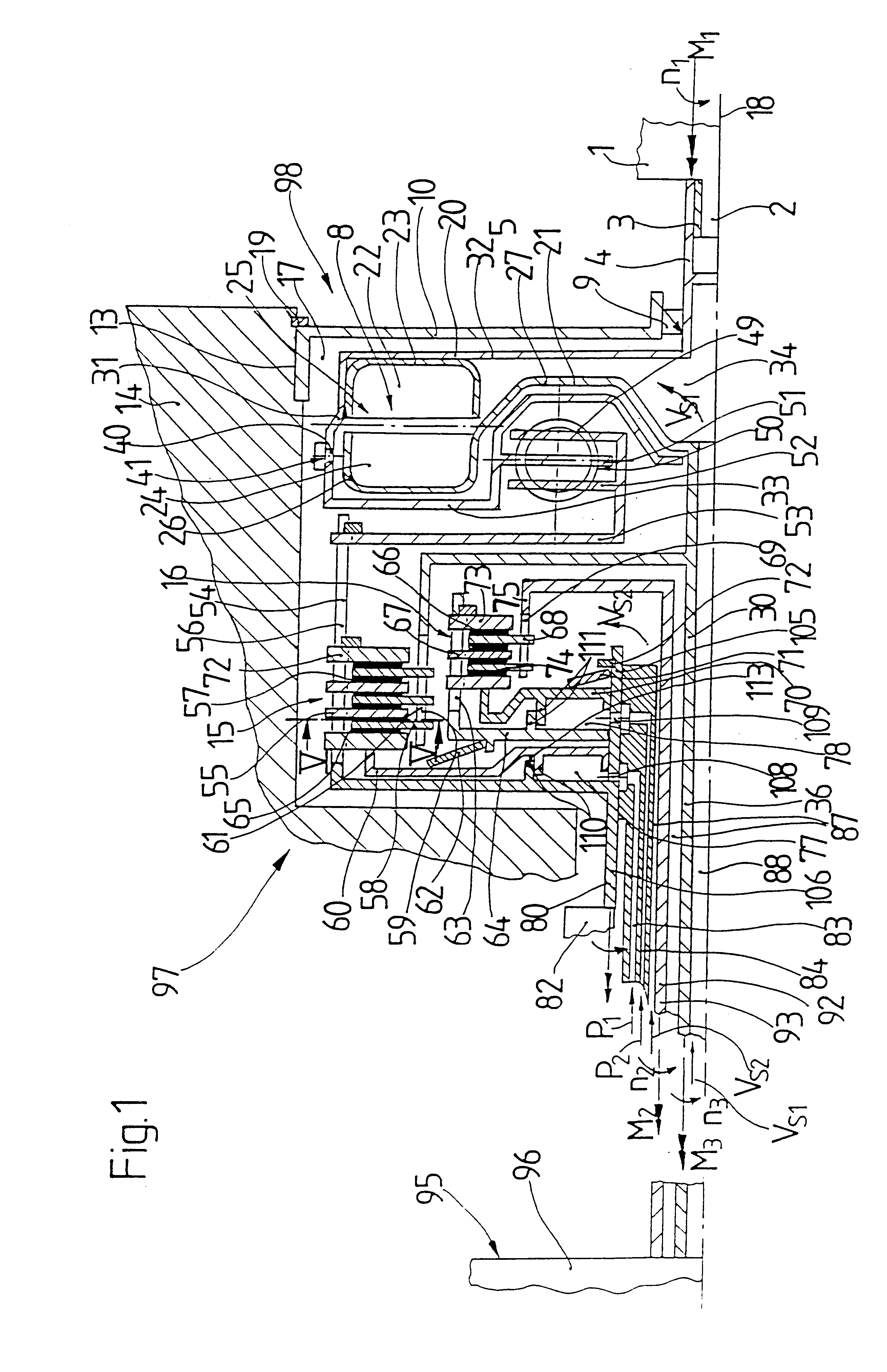
FIG. 1 shows a drive 1 which can be formed by an internal combustion engine of a motor vehicle. This drive 1 is provided with a crankshaft 2 which is connected via a toothing 3 with a hollow shaft 4 of an enclosure 5 for a hydrodynamic clutch 8 so as to be fixed with respect to rotation relative to it. The hollow shaft 4 has a seal 9 which is enclosed in turn by a cover 10 of a housing 14. The cover 10 is recessed into a depression 13 of the housing 14 in the radial outer area and is secured in the axial direction by the axial boundary of the depression 13 at one end and by a counter-holder 19 at the other end. The cover 10 defines a space 17 at its side facing the drive 1 which serves to receive the hydrodynamic clutch 8, mentioned above, and two friction clutches 15, 16. Together with the friction clutches 15, 16, the hydrodynamic clutch 8 forms a clutch device 97 which cooperates with the drive 1 and a shift transmission 95 as the drivetrain 98 of a motor vehicle. The hydrodynami...


PUM


Abstract

A clutch device which serves to connect the drive) of a motor vehicle with a multiple-speed shift transmission has, for this purpose, two friction clutches which can be engaged or disengaged independently from one another in that they are connected via their respective driven sides with a transmission input shaft. At least one of the friction clutches is in a working connection at its drive side with a driving member of a hydrodynamic clutch which can be activated at least under predetermined operating conditions of the drivetrain for transmitting torque introduced by the drive. At the same time, a driven member of the hydrodynamic clutch can be connected with one of the transmission input shafts.

Description

1. Field of the InventionThe invention is directed to a clutch device for connecting a motor vehicle drive with a multiple-speed transmission via at least two friction clutches which are connected with associated shift transmission input shafts by respective driven sides such that the clutches can be engaged or disengaged independently of one another.2. Description of the Related ArtA clutch device of this kind is known, for example, from EP 0 931 951 A1. The clutch device serves to connect the drive of a motor vehicle with a multiple-speed transmission via two friction clutches which are preferably automatically actuated, a clutch release system being associated with each of these friction clutches so that the two friction clutches can be engaged or disengaged independently from one another. One of the friction clutches is arranged on a central transmission input shaft so as to be fixed with respect to rotation relative to it, while the other friction clutch engages at a second tra...

Claims


Application Information

Patent Timeline
Patent Type & Authority Patents(United States)
IPC IPC(8): F16D25/0638F16D25/06F16D25/10F16D21/00F16D48/00F16D21/06F16D25/00F16D25/12F16D48/02
CPCF16D21/06F16D25/0638F16D25/10F16D25/14F16D48/02F16D25/12F16D2021/0661F16D48/0206F16D2500/1026F16D2500/10412F16D2500/1045F16D2500/50293F16D2500/5106F16D2500/70448F16D33/12F16D33/10F16D25/123F16D47/06F16D2048/0224F16D2048/0233F16D2300/14F16D2500/1082
Inventor KUNDERMANN, WOLFGANGSUDAU, JORG
Owner ZF FRIEDRICHSHAFEN AG
Why Eureka
Try Eureka