System and method for simulating circuits using inline subcircuits

a subcircuit and circuit simulation technology, applied in the field of computer simulators, can solve the problems of predefined output parameters and designer's inability to efficiently modify the output parameters of the models

Inactive Publication Date: 2002-04-30
CADENCE DESIGN SYST INC
View PDF7 Cites 52 Cited by
  • Summary
  • Abstract
  • Description
  • Claims
  • Application Information

AI Technical Summary

Problems solved by technology

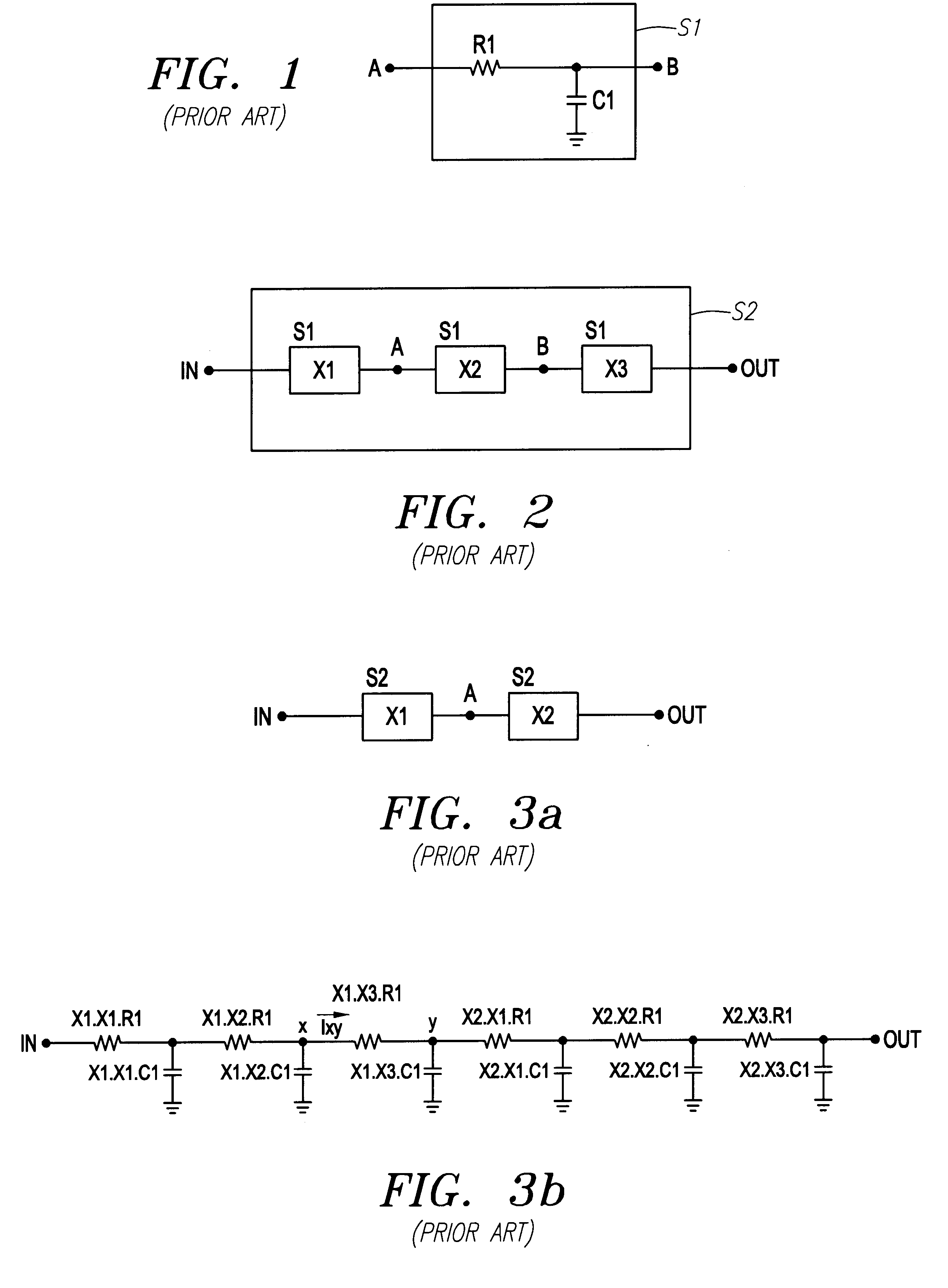
A problem with conventional hierarchical designs is that while a designer can design at various hierarchical levels to avoid implementation details, when the designer wants to test the design by simulating it, the designer must address the implementation details.
In addition, a problem with conventional models is that the output parameters are predefined.
Currently, a designer has no efficient technique for modifying the output parameters of the models.

Method used


Image

  • System and method for simulating circuits using inline subcircuits
  • System and method for simulating circuits using inline subcircuits
  • System and method for simulating circuits using inline subcircuits

Examples


example

(13)

One advantage of this embodiment is that the model that is used for a device can be changed from a built-in model to a user defined subcircuit model without the need to change the display setup in the CAD environment for the simulation result. The designer can create the new subcircuit model to behave like the built-in model.

As indicated above, the present invention enables output parameters to be added to otherwise conventional subcircuits, in addition to inline subcircuits.

Another advantage is that the designer can define output parameter or operating point information using algebraic expressions involving predefined operating points of components in the subcircuit, subcircuit input parameters, global simulator parameters such as temperature, or other information available from the simulator, for example. In addition, where nested subcircuits or inline subcircuits are used, the user-defined output parameters for an inner subcircuit definition can also be combined in the algebr...


PUM


Abstract

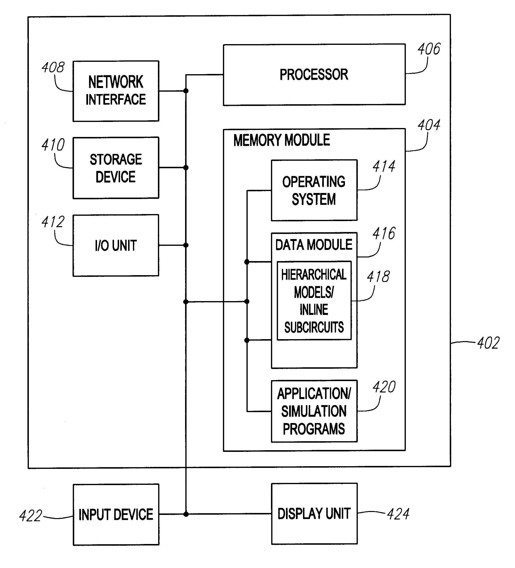
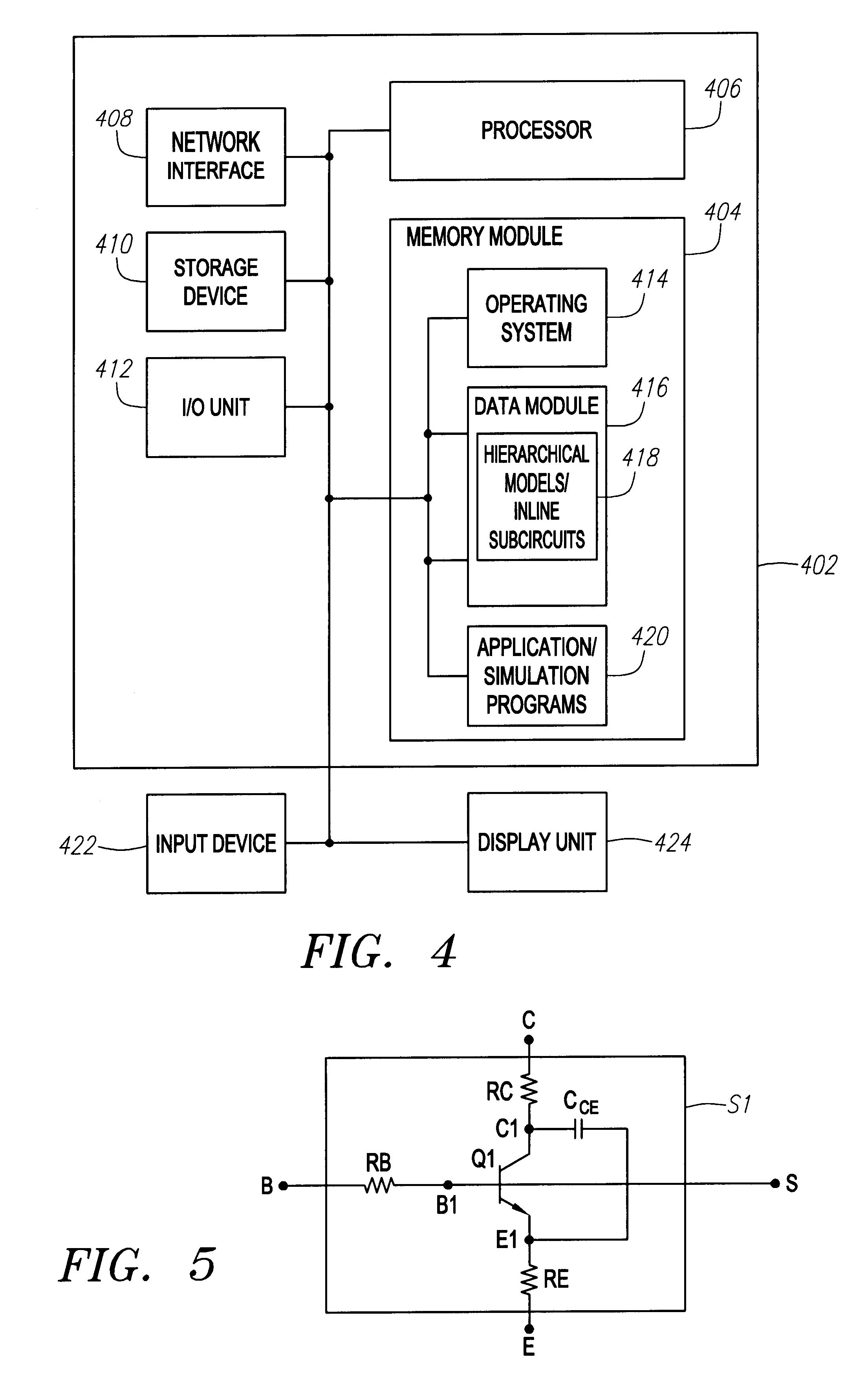
A system and method for generating inline subcircuits that enable a circuit designer to model and simulate circuits that when compared to conventional system and methods reduces the hierarchy from the perspective of the circuit designer, more efficiently models parasitic components, more efficiently parameterizes device models, more effectively creates models that are compatible with other simulation tools, can change the interface of a component without requiring the designer to use an extra layer of hierarchy, provides a more efficient interface by hiding details from the designer, enables hidden monitors and other functional designs to be automatically simulated by hiding these functions from the designer in a design level that is below the design level that is of interest to the designer, such as the geometrical parameter design level, can perform general purpose model binning with automatic selection, can export models and model parameters to other hierarchies without requiring an additional hierarchy in the model name, can allow sharing of exported parameterized models by devices or components that are not within the inline subcircuit definition and can modify or create outputs for models by redefining or hiding existing outputs or creating new outputs.

Description

1. Field of the InventionThe present invention relates to the field of computer simulators and more precisely to the field of analog, digital and mixed-signal circuit simulation and modeling.2. Description of Background ArtDesigners of electronic circuits frequently use various techniques to test and modify their designs. One conventional technique is to use computer software to create a circuit design by placing electronic representations of components (component models) in their design. After completing a first design, the design can be simulated to ensure proper functionality. One benefit of simulating circuits before manufacturing is to ensure the circuit functions properly in response to many potential input signals and in a wide variety of operating environments, for example. By identifying and correcting design errors before manufacturing the circuit, a significant savings in terms of both time and expense is achieved.When modeling and simulating circuits, e.g., analog, digit...

Claims


Application Information

Patent Timeline
Patent Type & Authority Patents(United States)
IPC IPC(8): G06F17/50
CPCG06F17/5036G06F30/367
Inventor O'RIORDAN, DONALD J.GHIJSEN, WALTER J.KUNDERT, KENNETH S.
Owner CADENCE DESIGN SYST INC
Why Eureka
Try Eureka