Fuel cutoff valve and production method thereof

a technology of fuel cutoff valve and production method, which is applied in the direction of valve housing, valve actuation float, machine/engine, etc., can solve the problems of poor seal and difficulty in simultaneously providing a better seal

Inactive Publication Date: 2002-05-07
TOYODA GOSEI CO LTD
View PDF5 Cites 16 Cited by
  • Summary
  • Abstract
  • Description
  • Claims
  • Application Information

AI Technical Summary

Benefits of technology

The valve body housed within this valve chest rises and falls with changes in buoyant force produced by changes in fuel level within the fuel tank. When the valve body rises due to buoyant force, it closes off the fuel conduit, preventing outflow of fuel from the tank. The cover is made of a resin material that is thermally weldable to the top of the tank, and is mounted onto the tank by means of thermal welding to the upper tank wall. In this way, the need for a fastening member on the top of the fuel tank is obviated, allowing for easy mounting of the fuel cutoff valve.
Additionally, the present invention provides for the combination of a fuel tank comprising a resin upper tank wall having a fixation hole and a fuel cutoff valve mounted on the upper tank wall by insertion thereof partway into the fixation hole. The fuel cutoff valve has a cover, a casing and a valve body such that the upper portion of the casing constitutes an insert member having a plurality of sealing ribs projecting substantially vertically towards the cover and a stopper formation extending at substantially right angles to the sealing ribs. The cover is unified with the upper portion of the casing by means of overmolding such that the sealing ribs and stopper formation are embedded in the cover. The cover is fabricated of a first resin material that is thermally weldable to the upper tank wall and has a welding end for thermal welding onto the upper tank wall. As with all embodiments and modifications of the present invention, the cover may have a passageway that connects to or may be part of the fuel conduit connecting the interior of the fuel tank to the outside, thus facilitating fuel vapor removal. The casing is made of a second resin material different from the first resin material, and is provided with a valve chest connecting the fuel tank interior with the fuel conduit including a connecting passage of the casing which then connects to a tubular member or other passageway in the cover. The valve body is housed within the valve chest and opens or closes off the fuel conduit depending on the fuel level in said fuel tank.

Problems solved by technology

Conversely, if the gap is made larger in order to facilitate assembly, a poor seal will result.
The conventional fuel cutoff valve 100 thus has the drawback that it is difficult to simultaneously provide a better seal while attempting to improve the ease of assembly.

Method used


Image

  • Fuel cutoff valve and production method thereof
  • Fuel cutoff valve and production method thereof
  • Fuel cutoff valve and production method thereof

Examples


first embodiment

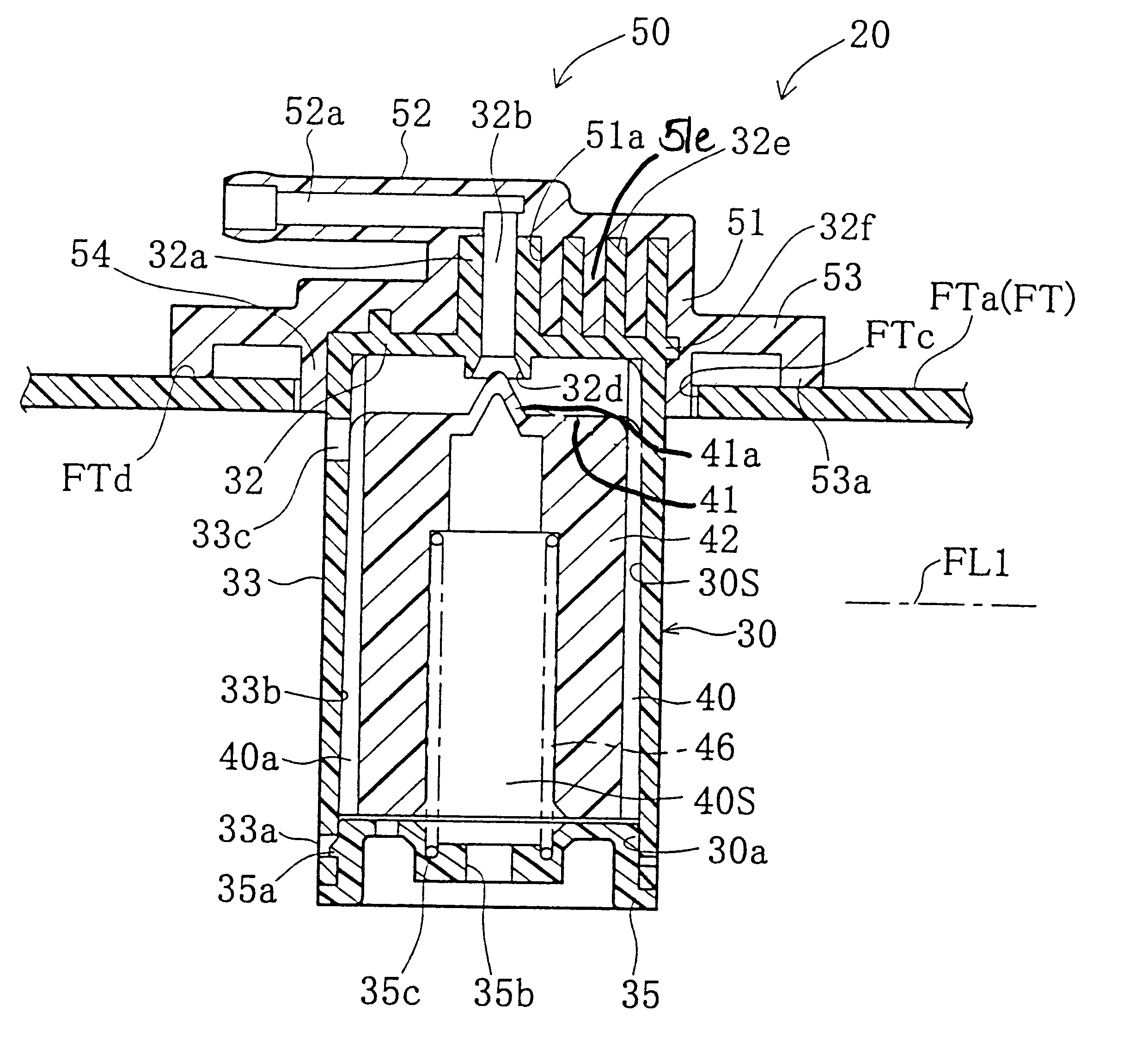
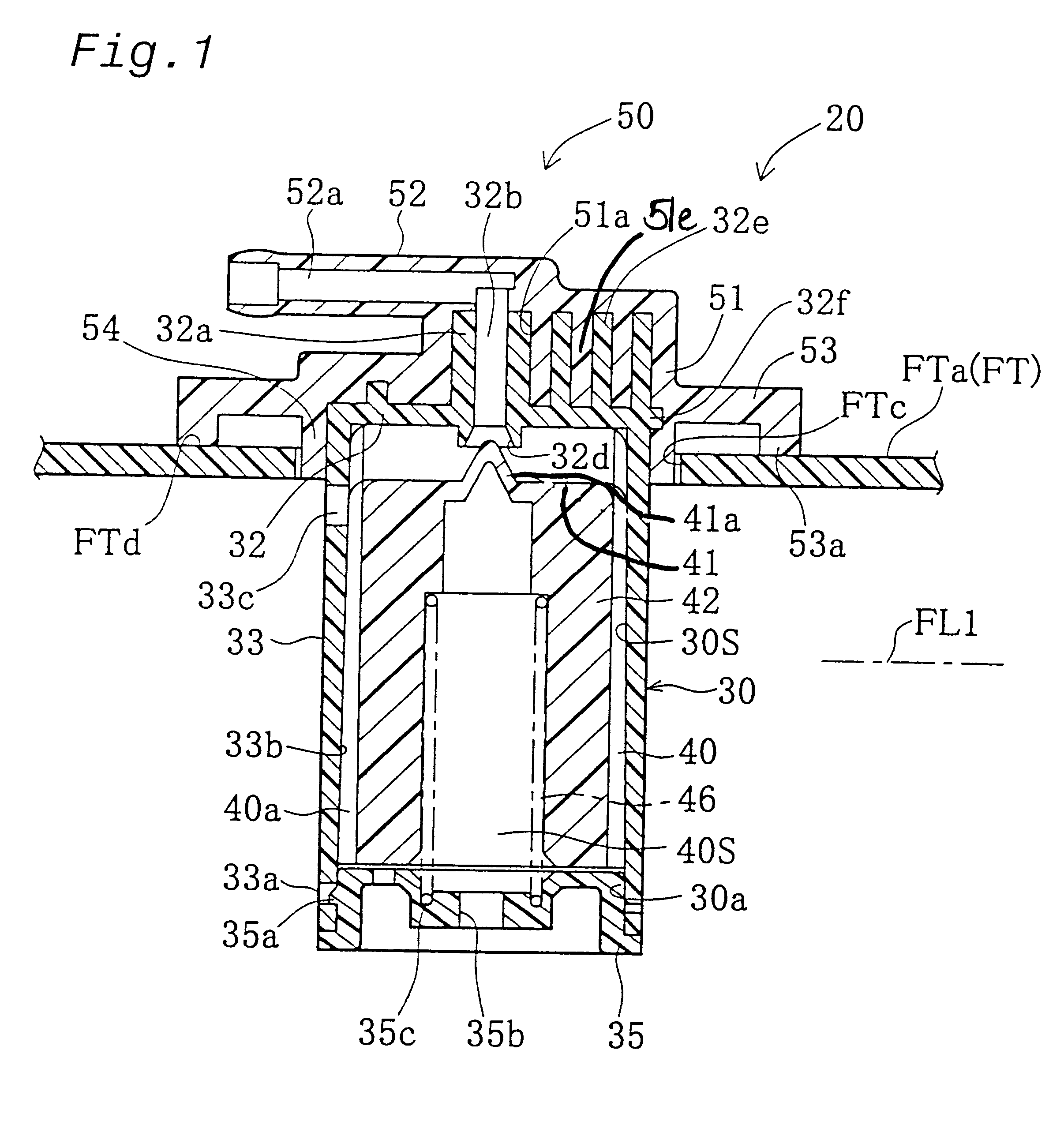
FIG. 1 is a sectional view showing a fuel cutoff valve 20 pertaining to the invention, mounted on top of an automobile fuel tank FT. In FIG. 1, the surfaces of fuel tank FT are made of a composite resin that includes polyethylene. A fixation hole FTc is provided in the upper tank wall FTa thereof. The fuel cutoff valve 20 is mounted on upper tank wall FTa with the lower portion thereof inserted into fixation hole FTc. During filling, when the fuel in fuel tank FT reaches a predetermined level FL1, fuel cutoff valve 20 prevents outflow thereof to the outside (canister).

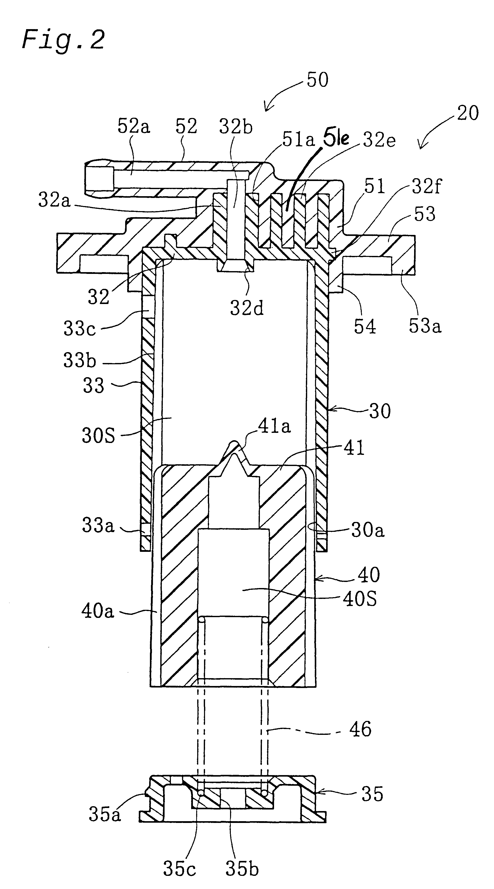
FIG. 2 is an exploded sectional view of the fuel cutoff valve 20. The fuel cutoff valve 20 comprises the principal elements of a casing 30, a base plate 35, a float 40, a spring 46, and a cover 50. The casing 30, base plate 35, and float 40 preferably are made of polyacetal synthetic resin, which has excellent resistance to fuel oil permeation. The cover member 50, on the other hand, preferably consists of polyethylene...

third embodiment

FIGS. 9 and 10 show another cutoff valve exemplifying a FIG. 9 shows a plan view of casing 30C, and FIG. 10 is a side view of casing 30C. In FIGS. 9 and 10, a plurality of sealing ribs 32Ce projecting upward towards cover are provided in the upper portion of casing 30C. The sealing ribs 30C include first through third annular portions 32e-1, 32e-2, and 32Ce-3. A stopper hole 32Cd is formed in the third annular portions 32Ce-3 and serves as the stopper formation. As the stopper hole 32Cd becomes filled with the resin of the cover after fabrication of the cover by overmolding, the casing 30C may be attached more securely to the cover.

In the preceding embodiments, the casing 30 is employed as an insert member, but this is not limiting, since it is possible to use the cover 50 as an insert member. When the casing is used as the insert member, the casing is provided with sealing ribs 32e and a stopper formation, whereas, the cover has a mating portion 51a formed during the overmolding p...


PUM


Abstract

A fuel cutoff valve and a method for making the same having a simpler mounting operation and excellent sealing properties are disclosed. The fuel cutoff valve includes a cover, a casing made of a different resin than the cover wherein the casing includes a valve chest and a valve body accommodated in the valve chest. The casing is used as an insert member having a plurality of sealing ribs projecting substantially vertically towards the cover, and a stopper formation forming a substantially horizontal step at substantially right angles to the sealing ribs, and the cover is integrally formed therewith so as to enclose the sealing ribs and stopper formation of the casing. The fuel cutoff valve may also be constructed such that the cover is used as the insert member as opposed to the casing. The stopper formation can be a rib, a recess or a through-hole.

Description

1. Field of the InventionThe present invention relates to a fuel cutoff valve for mounting onto the upper wall of a fuel tank to open and close a fuel conduit that connects the fuel tank to the outside to facilitate removal of fuel vapors from the fuel tank.2. Description of Related ArtFuel cutoff valves of this kind are known in the art, being described in JPA 11-315765, which has the structure depicted in FIG. 11. As will be apparent from the sectional view in FIG. 11, the fuel cutoff valve 100 is mounted on the upper tank wall FTa of a fuel tank FT, and comprises a casing 102, a cover 110, a float 120, and a spring 130. The casing 102 comprises a top wall 103, a side wall 104 integrally formed with outside edge of top wall 103, and a base plate 105 attached to the bottom end of side wall 104 so as to define an internal space constituting a valve chest 102S. Within valve chest 102S is housed a float 120 having a valve portion 120a in its upper portion. This valve portion 120a open...

Claims


Application Information

Patent Timeline
Patent Type & Authority Patents(United States)
IPC IPC(8): B60K15/035B60K15/03F16K24/04F16K24/00B60K15/01F02M37/00F16K27/00
CPCF16K24/044B60K15/03519Y10T137/86324Y10T137/053Y10T137/3099Y10T137/0874
Inventor SUGIZAKI, TOMOHIRONOJIRI, MASANORI
Owner TOYODA GOSEI CO LTD
Why Eureka
Try Eureka