Trailing edge wedge for an aircraft wing

a technology for aircraft wings and railings, applied in the direction of wing adjustments, influencers by shock waves, wings, etc., can solve the problems of unavoidable structural tolerances and related asymmetric characteristics of aircraft, and the aircraft cannot compensate for asymmetric aircraft characteristics caused by unavoidable structural tolerances

Inactive Publication Date: 2002-05-07
DAIMLER CHRYSLER AEROSPACE AIRBUS
View PDF4 Cites 21 Cited by
  • Summary
  • Abstract
  • Description
  • Claims
  • Application Information

AI Technical Summary

Benefits of technology

The present edge wedge advantageously influences the pressure distribution on the upper wing surface and the bottom wing surface where the edge wedge is secured to bottom surface of the wing. The present edge wedge functions as a divergent trailing edge of the wing whereby a desirable localized lift increase is achieved which in turn causes a desired counter rolling moment for compensating any asymmetric characteristics of the aircraft or of its flight. Another advantage of the invention is seen in that the desired rolling moment or rather counter-rolling moment can be selected by varying the width of the edge wedge in the direction of the span width or length of the wing to which the edge wedge is attached. Thus, the present edge wedge provides a flexible means for an advantageous compensation not only of asymmetrical characteristics of the aircraft itself that are due to unavoidable structural tolerances but also compensates for asymmetric flight characteristics that may occur unintentionally particularly during cruising flight of an aircraft. The wedge width in the wing span direction is selected according to the desired counter rolling moment.
is seen in that the desired rolling moment or rather counter-rolling moment can be selected by varying the width of the edge wedge in the direction of the span width or length of the wing to which the edge wedge is attached. Thus, the present edge wedge provides a flexible means for an advantageous compensation not only of asymmetrical characteristics of the aircraft itself that are due to unavoidable structural tolerances but also compensates for asymmetric flight characteristics that may occur unintentionally particularly during cruising flight of an aircraft. The wedge width in the wing span direction is selected according to the desired counter rolling moment.
In order that the invention may be clearly understood, it will now be described in connection with example embodiments, with reference to the accompanying drawings, wherein:
FIG. 1 shows a schematic sectional view through a trailing edge portion of an aircraft wing equipped with an edge wedge according to the invention; and
FIG. 2 is a view similar to that of FIG. 1, however with a curved edge wedge outer downwardly facing surface.
DETAILED DESCRIPTION OF PREFERRED EXAMPLE EMBODIMENTS AND OF THE BEST MODE OF THE INVENTION

Problems solved by technology

While the conventional wedge component improves the lift coefficient and reduces the drag during cruising flight, it does not provide any compensation for unavoidable structural tolerances and related asymmetric characteristics of the aircraft.
Asymmetric aircraft characteristics caused by unavoidable structural tolerances are not compensated by such bail edges on the ailerons.

Method used


Image

  • Trailing edge wedge for an aircraft wing
  • Trailing edge wedge for an aircraft wing
  • Trailing edge wedge for an aircraft wing

Examples


Embodiment Construction

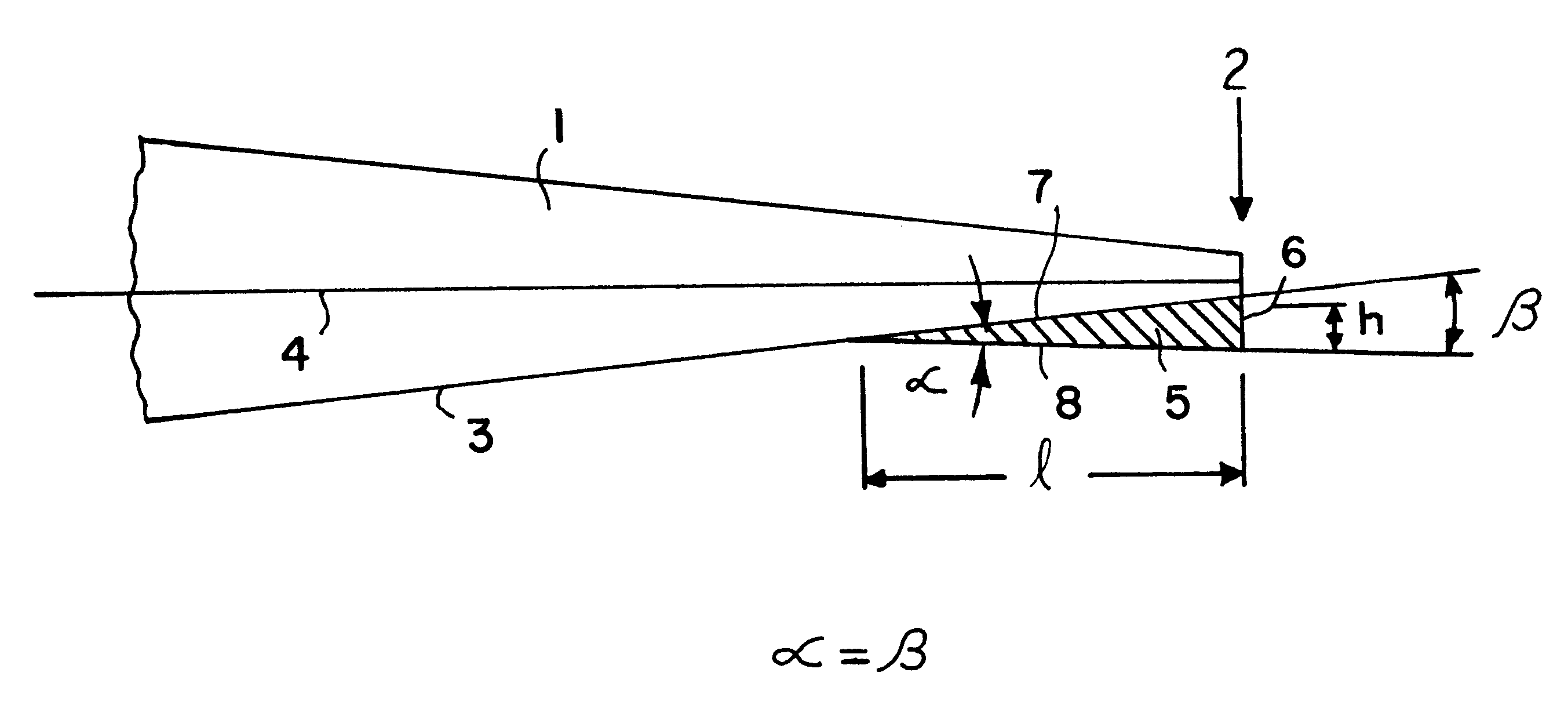
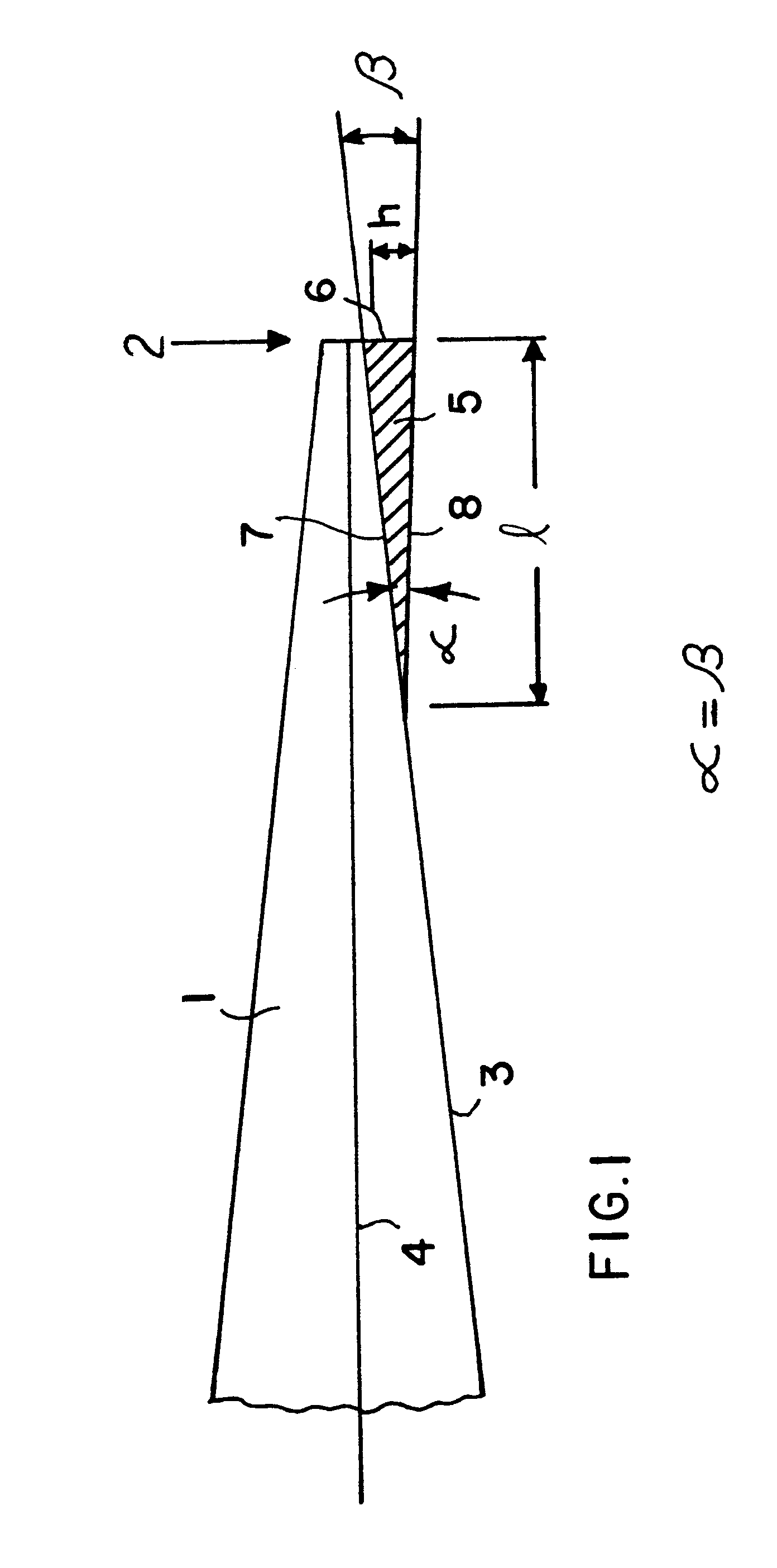
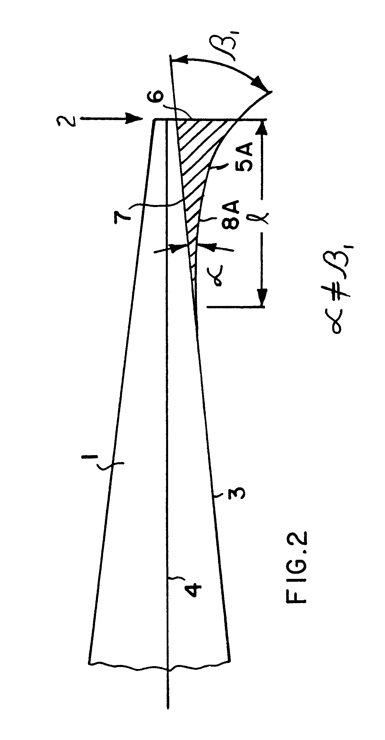
FIG. 1 shows the attachment of an edge wedge 5 according to the invention directly to the bottom surface 3 of an aircraft wing 1 along the trailing edge 2 of the wing. The edge wedge 5 has an inner surface connected to the bottom wing surface 3 and an outer surface 8 facing downwardly. The edge wedge 5 further has a back end wedge surface 6 having a height h which is preferably positioned in the same plane as the trailing edge surface of the wing 1. The edge wedge 5, specifically its bottom surface 8 has a length 1 in the longitudinal chord direction.

A wedge angle .alpha. is enclosed between the inner and outer surfaces 7 and 8 of the edge wedge 5. The angle .alpha. is also determined by the ratio of the height h to length 1 of the bottom surface 8 of the edge wedge 5. This length 1 is measured in the longitudinal direction of the chord axis 4 of the wing 1 between its leading and trailing edges. The wedge angle .alpha. according to the invention is within the range of about 5.degre...


PUM


Abstract

A trailing edge wedge for an aircraft wing is attached to a bottom downwardly facing wing surface along the trailing edge of the wing so that an inner edge wedge surface is fully covered by the bottom wing surface. When the edge wedge is secured to a bottom surface of a wing, the wedge tip faces in the flight direction. The inner edge wedge surface and an opposite outer edge wedge surface enclose a wedge angle within the range of about 5° to about 20°. The edge wedge compensates for asymmetric aircraft characteristics due to unavoidable manufacturing tolerances.

Description

PRIORITY CLAIMThis application is based on and claims the priority under 35 U.S.C. .sctn. 119 of German Patent Application 198 54 741.2, filed on Nov. 27, 1998 the entire disclosure of which is incorporated herein by reference.The invention relates to a wedge element for attachment to a bottom surface of an aircraft wing directly along the trailing edge of the wing whereby the wedge element referred to herein as edge wedge preferably extends in parallel to the trailing edge of the wing.BACKGROUND INFORMATIONU.S. Pat. No. 4,542,868 (Boyd) discloses a wedge-shaped structural component for attachment to the bottom surface of an aircraft wing profile near or along the trailing edge of the aircraft wing. The purpose of such a conventional wedge shaped structural component is to improve the lift coefficient and to reduce the drag during cruising speeds. The conventional wedge-shaped component has a downward height within the range of 0.5% to 1.5% of the local chord of the aircraft wing. T...

Claims


Application Information

Patent Timeline
Patent Type & Authority Patents(United States)
IPC IPC(8): B64C23/00B64C23/04B64C5/08B64C5/00B64C3/14B64C3/00B64C3/58
CPCB64C3/14B64C3/58B64C23/04Y02T50/12B64C2003/147Y02T50/10
Inventor BRINK, BERNARD KOCK AM
Owner DAIMLER CHRYSLER AEROSPACE AIRBUS
Why Eureka
Try Eureka