Transparent laminate

a technology of transparent laminates and laminates, applied in the field of transparent laminates, can solve the problems of inability to achieve practicability, inability to reduce visibility through impact positions, and inability to meet the impact resistan

Inactive Publication Date: 2002-05-14
SUMITOMO CHEM CO LTD
View PDF8 Cites 33 Cited by
  • Summary
  • Abstract
  • Description
  • Claims
  • Application Information

AI Technical Summary

Problems solved by technology

However, in these transparent plates, there is a problem that for improving impact resistance, an increase in thickness is required, and consequently their weight increases, which often leads to a lack of practicability.
However, in the above-described prior technologies, when the plate receives an impact several times repeatedly, the impact resistance thereof is not satisfactory.
Namely, though a protective ability against a strong impact can be manifested sufficiently, when the plate receives an impact several times, particularly when the plate receives an impact several times at the same position, small fragments are often scattered from parts around the impact position with such small fragments being deleted from the impact position of the transparent plate, to thereby cause the possibility of a decrease in visibility through the impact position.

Method used


Image

  • Transparent laminate
  • Transparent laminate
  • Transparent laminate

Examples


example 1

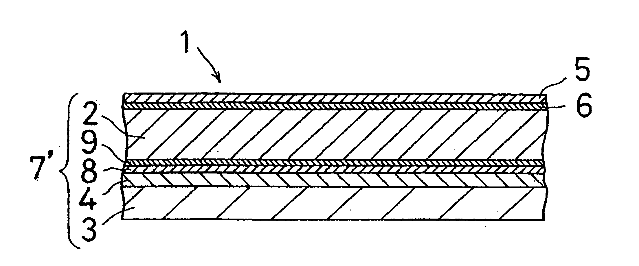
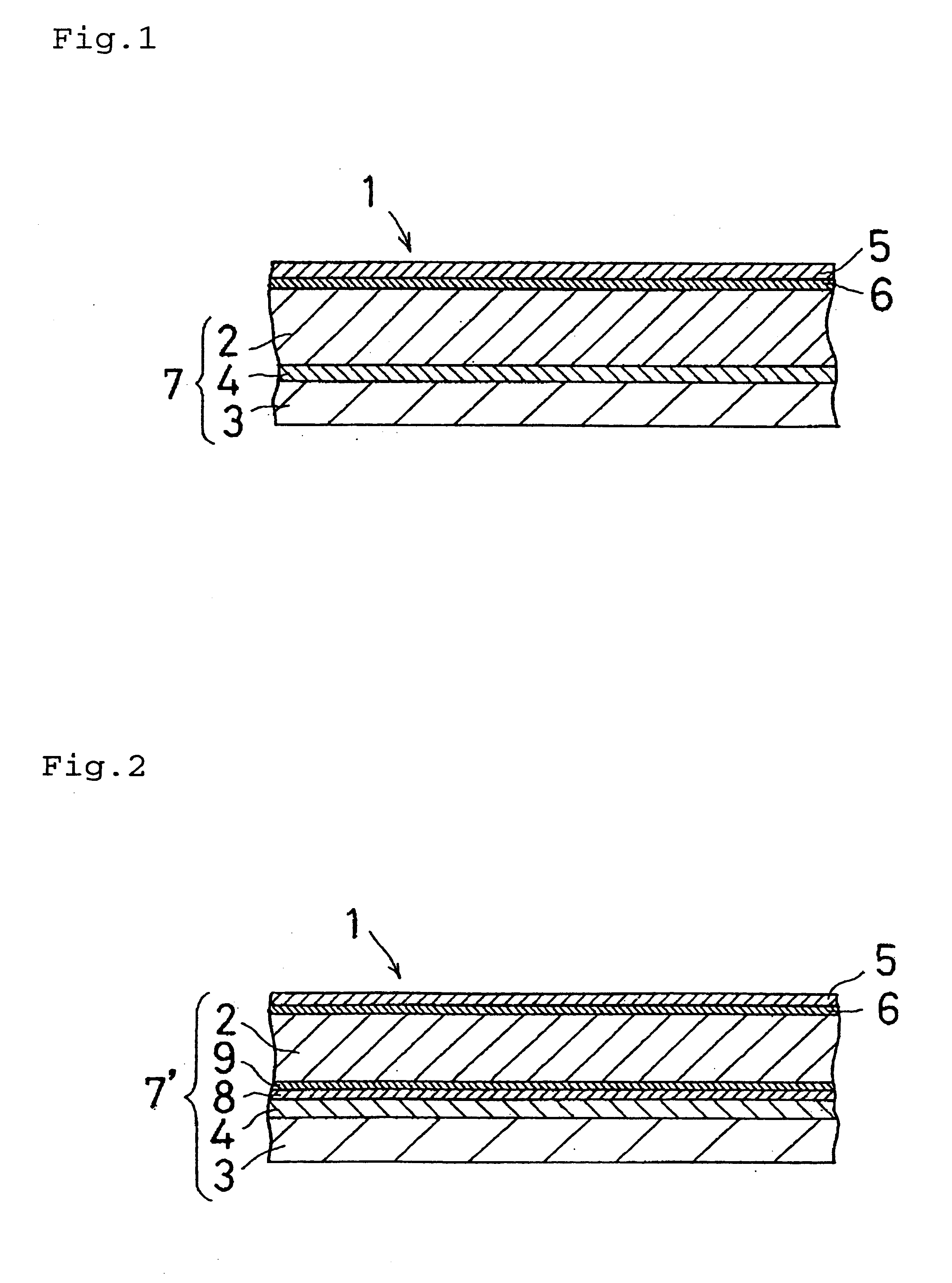
The polycarbonate-based resin plate B was placed facing one surface of the acrylic resin plate A at a certain distance, the acrylic resin film B ("Sunduren.RTM. 002ANTB") was inserted between them, and they were pressed for 1 minute by a press molding machine at a heat plate temperature of 150.degree. C., a preheating time of 2 minutes and pressing pressure of 50 kgf / cm.sup.2.sub.1 then, pressed for 4 minutes in a cooling press at a pressing pressure of 50 kgf / cm.sup.2, to bond the polycarbonate-based resin plate B (surface layer(5)) via the acrylic resin B (surface bonding layer(6)) to the acrylic resin plate A (first substrate(2)).

Then, the polycarbonate-based resin plate A (second substrate(3)) was placed facing the other surface of the acrylic resin plate A (first substrate(2)) at an distance of 2 mm. The distance was provided by inserting a soft vinyl chloride hose having a thickness of 2 mm between the acrylic resin plate A (first substrate(2)) and the polycarbonate-based resi...

example 2

The polycarbonate-based resin plate B (surface layer(5)) was placed facing one surface of the acrylic resin plate A (first substrate(2)) at a certain distance, the acrylic resin film B ("Sunduren.RTM. 002ANTB") was inserted between them, this sandwich was placed in a vacuum bag, air in the vacuum bag was exhausted at an atmosphere temperature of 135.degree..pi.C. to adhere them temporarily. Then, the sandwich was place in the autoclave, heated from room temperature at atmospheric pressure to 150.degree. C. at 9 atm. over 60 minutes and the temperature and the pressure were kept for 30 minutes, then, cooled down to room temperature at atmospheric pressure over 50 minutes, to bond the polycarbonate-based resin plate B (surface layer(5)) via the acrylic resin B (surface bonding layer(6)) to the acrylic resin plate A (first substrate(2)).

Then, the polycarbonate-based resin plate A (second substrate(3)) was bonded via the bisphenol type epoxy-based cured resin layer(first bonding layer(4...

example 3

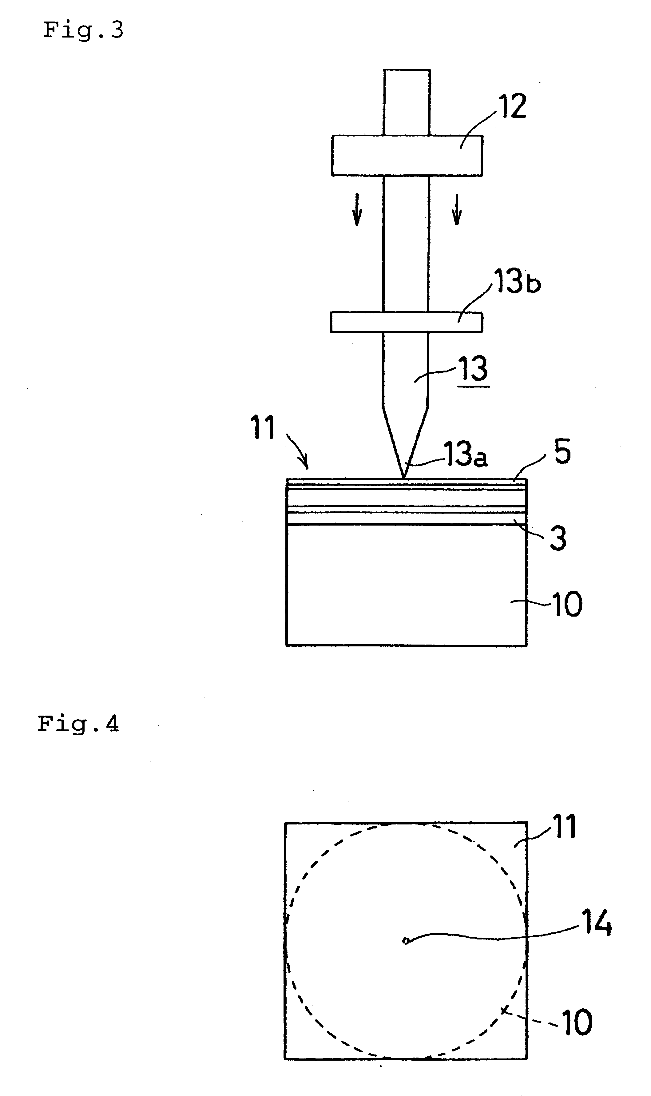
A transparent laminate was obtained in the same manner as in Example 1 except that the acrylic resin plate C was used instead of the acrylic resin plate A as the first substrate(2). This plate had excellent transparency, and when it received impact several times at the same position, the impact position revealed almost no whitening.

The results of the evaluation of the obtained transparent laminate are shown in Table 1.


PUM

PropertyMeasurementUnit
Tgaaaaaaaaaa
thicknessaaaaaaaaaa
thicknessaaaaaaaaaa

Abstract

The present invention provides a transparent laminate comprising a laminate substrate obtained by bonding a Second substrate composed of a polycarbonate-based resin to a first surface of a first substrate composed of an acrylic resin via a first bonding layer composed of a resin having a glass transition temperature(Tg) of about 50° C. or less, and a surface layer composed of a polycarbonate-based resin bonded via a surface bonding layer composed of an acrylic resin to a second surface of the first substrate, which laminate is light and excellent in transparency and excellent in impact resistance when it repeatedly receives an impact.

Description

1. Field of the InventionThe present invention relates to a transparent laminate excellent in impact resistance which is suitably used as for example a bulletproof face guard, bulletproof shield, a glazing member of various vehicles, a partition board on a bank counter, a crime preventive door and the like.2. Description of the Related ArtA transparent plate having impact resistance is often used as a glazing member in public facilities, athletic facilities and the like, as a partition board on a bank counter and the like, as a glazing member of a crime-preventive door and the like, as a glazing member of various vehicles, as well as for other materials and applications.As such a transparent plate, there are known silicate glass plates, polycarbonate-based resin plates, and further, a transparent laminate obtained by bonding a silicate glass plate to a polycarbonate-Dased resin plate via a methacrylate-based syrup (USP 4,125,669), transparent laminates obtained by bonding a pluralit...

Claims


Application Information

Patent Timeline
Patent Type & Authority Patents(United States)
IPC IPC(8): B32B27/36B32B27/08F41H5/04F41H5/00
CPCB32B27/08B32B27/30B32B27/36F41H5/0407Y10T428/26Y10T428/24967Y10T428/254Y10T428/31928Y10T428/31507Y10T428/31515Y10T428/31935
Inventor OGURA, KOJIAMEKAWA, YOSHIHIDE
Owner SUMITOMO CHEM CO LTD
Why Eureka
Try Eureka