
Signal processing circuit of sensor

a processing circuit and sensor technology, applied in the direction of instruments, liquid/fluent solid measurement, fluid pressure measurement, etc., can solve the problems of large cost, small deviation in each product, complicated processing structure,

Inactive Publication Date: 2002-05-14
NAGANO KEIKI
View PDF12 Cites 16 Cited by
  • Summary
  • Abstract
  • Description
  • Claims
  • Application Information

AI Technical Summary

Problems solved by technology

Moreover, when the electro-capacitance sensors are mass-produced, slight deviation is caused in each product.
However, since such calibration work requires an outside adjusting device as well as the sensor and the calibration work has to be conducted for respective sensors, large cost is necessary for the calibration work after manufacturing the sensors.
However, there are following disadvantages in the above-described self-calibrating sensor.
Accordingly, the processor of the signal processing circuit needs to include both calculating section of the calibration values a, b and c by the formula (2) to (4) and output correcting section using the formula (5), resulting in complicated structure of the processor.
Moreover, the calibration values calculating section according to the formulas (2) to (4) is not used in the actual pressure measurement after calibration, inevitably resulting in unnecessary parts not used for the actual measurement.
Accordingly, even though the cost for the calibration work can be reduced, total cost including the cost for respective components is not necessarily reduced on account of complicated structure of the processor in the sensor.
Similar disadvantages also occur to a self-calibrating sensor, in which physical amount of the workpiece is electrically detected and an electric signal is outputted by detecting the change in a sensor element, such as a strain gauge sensor for detecting a deformation of a diaphragm as a change in a strain gauge, not limited to the above-described electro-capacitance sensor.

Method used


Image

  • Signal processing circuit of sensor
  • Signal processing circuit of sensor
  • Signal processing circuit of sensor

Examples


first embodiment

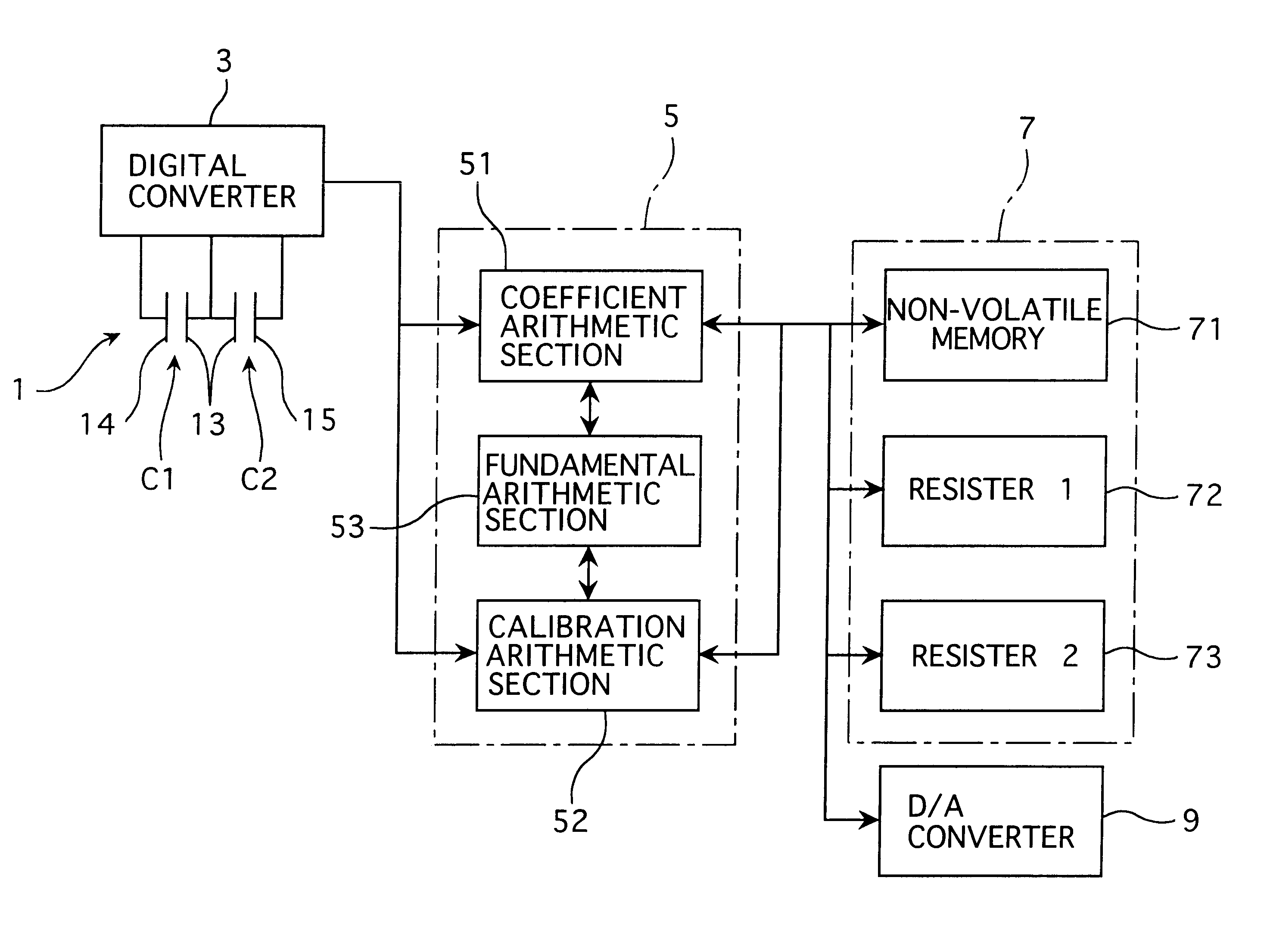
A sensor and signal processing circuit is shown in FIG. 4.

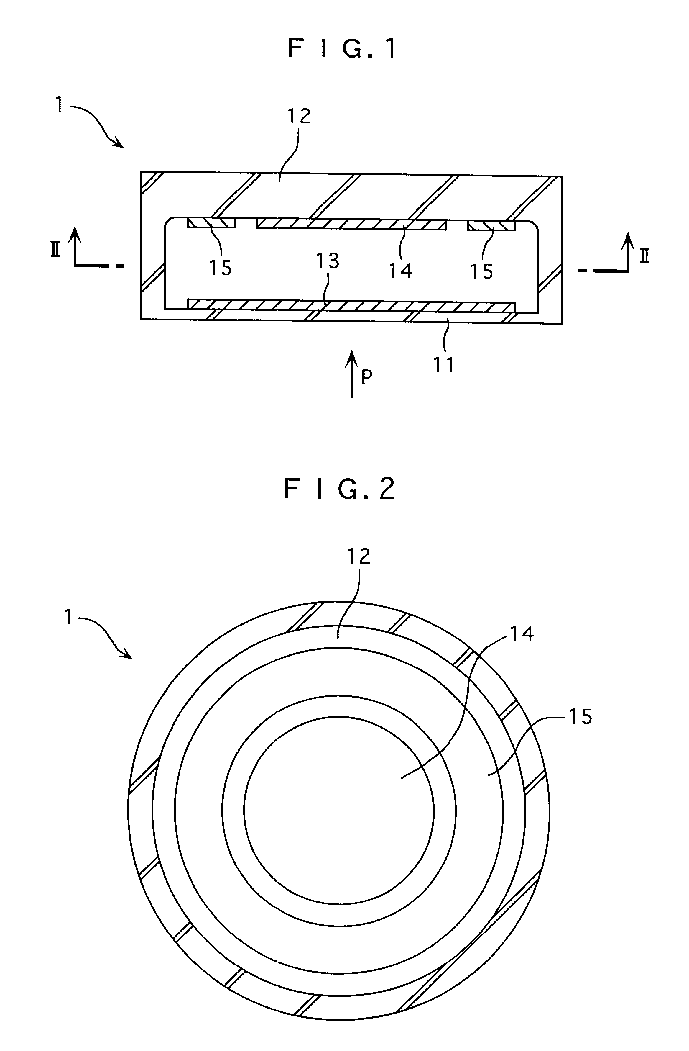
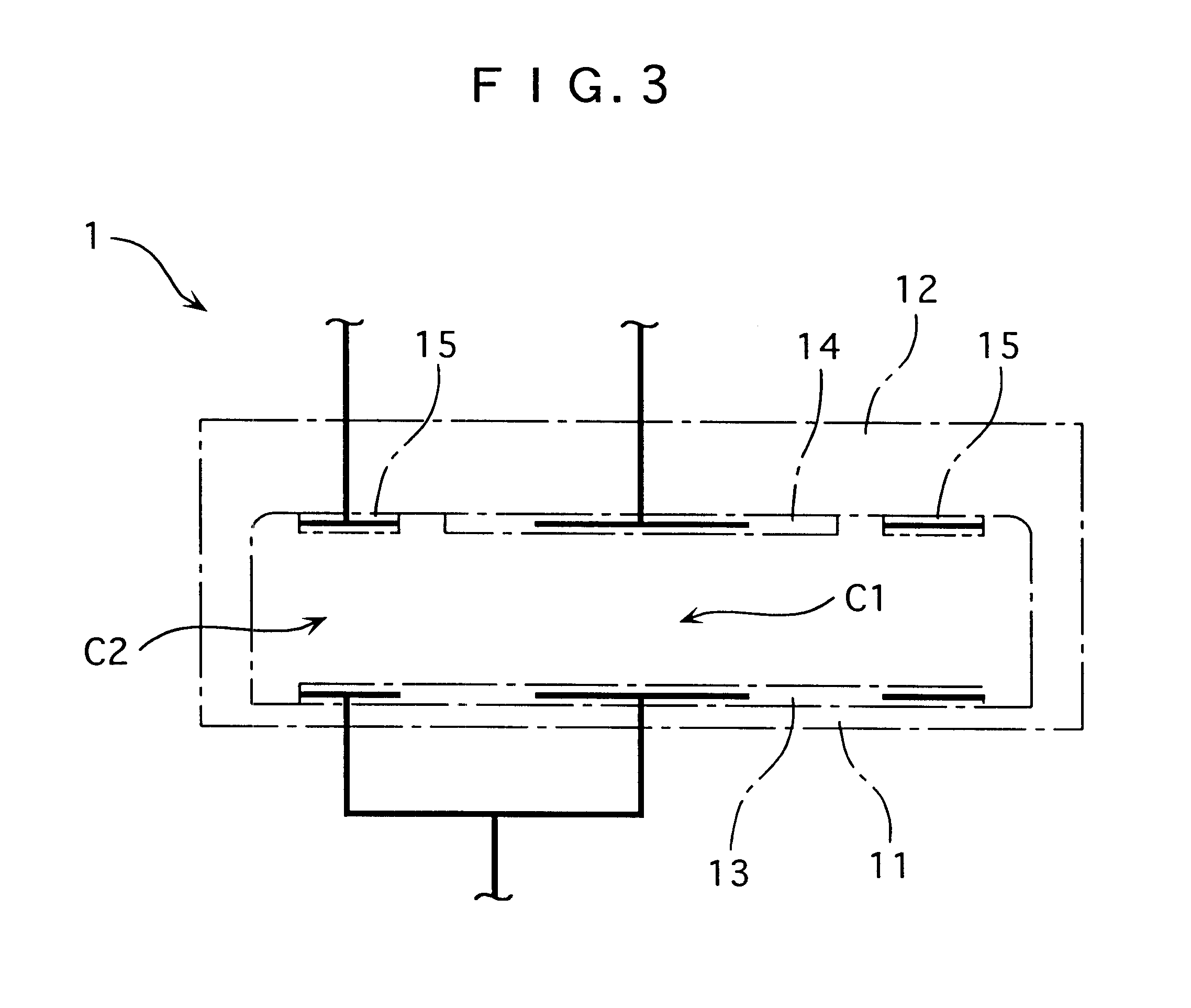
An electro-capacitance pressure sensor 1 shown in the aforesaid FIGS. 1 to 3 is provided with a processor 5 through a digital converter 3 as a signal output means, the processor 5 being connected to a memory 7 and a D / A converter 9 for outputting to the outside.

All of the digital converter 3, the processor 5, the memory 7 and the D / A converter 9 are composed of ASIC (Application Specific Integrated Circuit), which is installed integrally to the electro-capacitance pressure sensor 1. The electro-capacitance pressure sensor 1 is configured as a self-calibrating sensor which calculates calibration value and conducts calibration calculation based thereon.

The processor 5 includes a coefficient arithmetic section 51, a calibration arithmetic section 52 and a fundamental arithmetic section 53.

The coefficient arithmetic section 51 calculates coefficients .alpha., .beta. and .gamma. from known calibration pressure P.sub.0, P.sub.1 an...

second embodiment

of the present invention will be described below.

In the electro-capacitance pressure sensor 1 according to the above-described embodiment, the movable electrode 13 is provided on one surface of the diaphragm 11 and the first and the second fixed electrodes 14 and 15 are formed on the substrate 12 supporting the diaphragm 11 and opposing the movable electrode 13.

On the other hand, an electro-capacitance pressure sensor 101 according to the second embodiment has movable electrodes 113 formed on both sides of the diaphragm 111 as shown in FIG. 5. First fixed electrode 114 is provided opposedly to one of the movable electrodes 113 and second fixed electrode 115 is opposing the other one of the movable electrodes 113. The electro-capacitance pressure sensor 101 forms a differential pressure sensor of which diaphragm 111 deforms in proportion to a pressure difference P.sub.1 -P.sub.2, the pressure P.sub.1 and P.sub.2 acting on a space separated by the diaphragm 111.

The processor 5 integra...


PUM


Abstract

A processor of a signal processing circuit for calibrating an electro-capacitance pressure sensor includes a coefficient arithmetic section for calculating calibration value and a calibration arithmetic section. The calibration arithmetic section calculates an electro-capacitance ratio between electro-capacitance C1 and C2 detected by an electro-capacitance pressure sensor and conducts a calibration calculation from the electro-capacitance ratio to output a converted pressure value. The processor includes a fundamental arithmetic section for conducting a calculation given by f=(Z-W) / (X-Y) for predetermined arguments X, Y, Z and W input by the coefficient arithmetic section or the calibration arithmetic section and for outputting the calculation result f to the one of the coefficient arithmetic section and the calibration arithmetic section providing the input. The fundamental arithmetic section provides shared calculating for the coefficient calculation and calibration calculation.

Description

1.Field of the InventionThe present invention relates to a signal processing circuit for processing an electric signal of a sensor, the sensor having a sensor element for electrically detecting a change in physical amount of a workpiece and a signal output means for detecting the change of the sensor element and outputting the electric signal.2.Description of the Related ArtConventionally, a sensor having a sensor element for electrically detecting a change in a physical amount of a workpiece and a signal outputting means for detecting the change of the sensor chip and outputting an electric signal is used.For example, an electro-capacitance type sensor having a diaphragm deforming in proportion to a change in pressure of the workpiece, a substrate for supporting the diaphragm, a sensor element for detecting the deformation of the diaphragm as a change in electro-capacitance between the diaphragm and the substrate and an electro-capacitance signal output means for detecting the chan...

Claims


Application Information

Patent Timeline
IPC IPC(8): G01L27/00G01L9/00G01L9/12
CPCG01L27/002
Inventor TSUCHIYA, MUNENORIYAMAGISHI, KAZUYAOGAWA, SHIGEMITSU
Owner NAGANO KEIKI
Learn More