Dual filter

a filter and dual-layer technology, applied in the field of filters, can solve the problems of high expenditure and easy errors in the assembly of filters

Inactive Publication Date: 2002-05-21
MANN HUMMEL GMBH
View PDF8 Cites 68 Cited by
  • Summary
  • Abstract
  • Description
  • Claims
  • Application Information

AI Technical Summary

Problems solved by technology

Although, it is possible in this manner to arrange two, possibly different filter elements in a filter cartridge, as a result of the large number of i

Method used


Image

  • Dual filter
  • Dual filter
  • Dual filter

Examples


Embodiment Construction

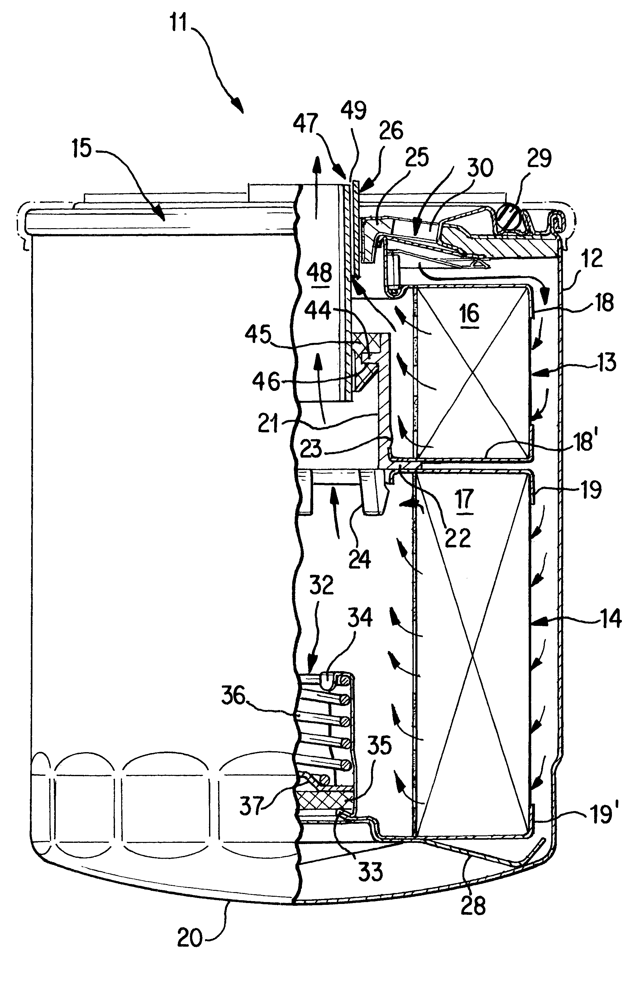
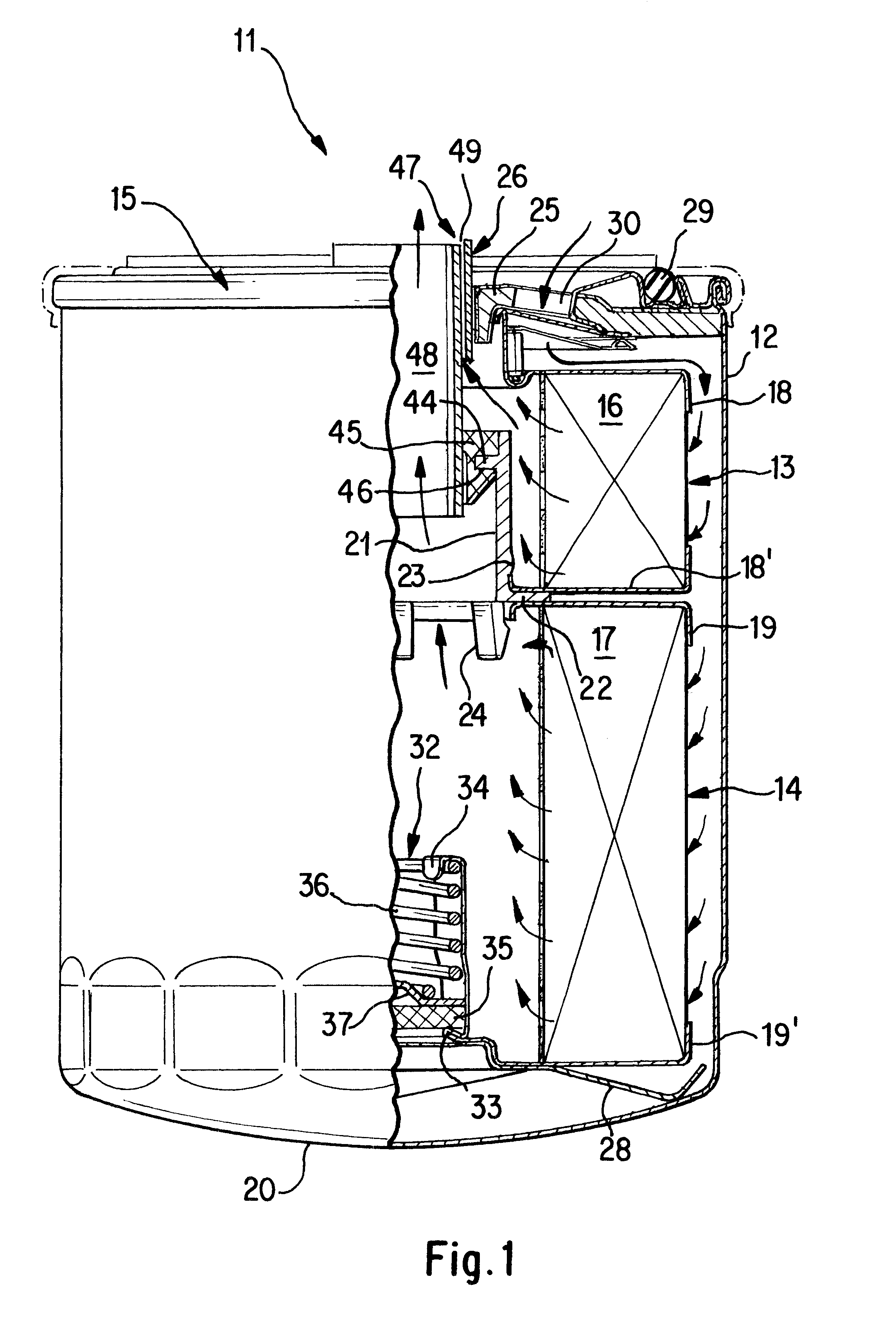
FIG. 1 is a partial sectional view of a filter 11 according to the invention in whose cylindrical housing 12 a fine filter 13 and a coarse filter 14 are arranged which are axially aligned with this housing 12. These filter elements are constructed in the manner of a hollow cylinder and extend along the largest portion of the inner clearance of the housing 12, the coarse filter 14 being approximately twice as long as the fine filter 13. The circular ring thickness and the radius of the filter elements 13 and 14 amount to approximately half the radius of the housing 12 and are identical in the case of both filter elements.

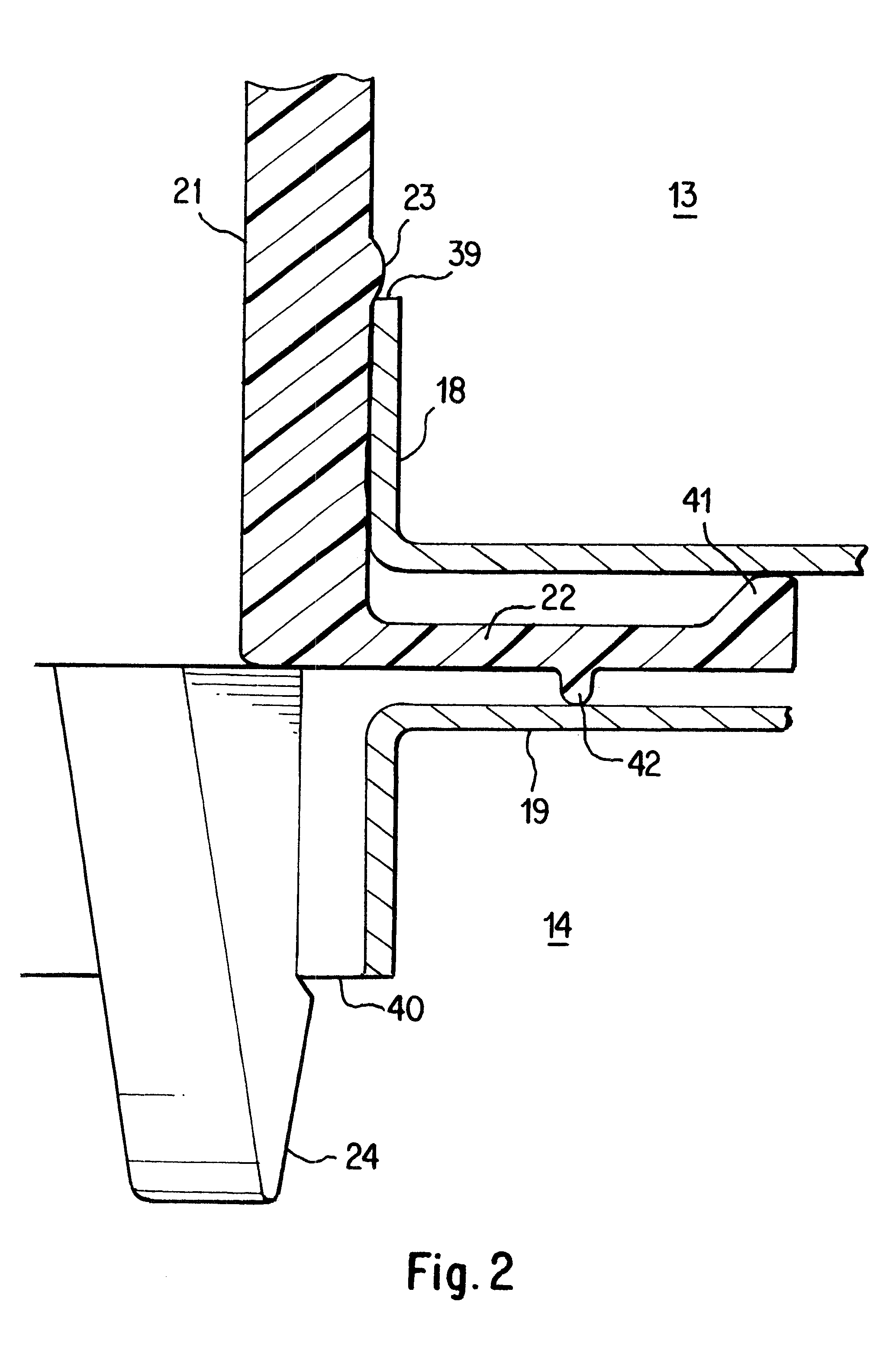
The fine filter 13 as well as the coarse filter 14 are constructed as cylindrical expansion bellows filters which each consists of fine and coarse filtering media 16 and 17; in this case, of a fine-paper and coarse-paper collar which each have end plates 18 and 18' as well as 19 and 19' on their end faces for the purpose of sealing. The end plates 18 and 19, which cl...


PUM

PropertyMeasurementUnit
Pressureaaaaaaaaaa
Diameteraaaaaaaaaa
Lengthaaaaaaaaaa

Abstract

Several filter elements (13, 14) for purifying a liquid are connected with a connecting piece (21) to form a single structural unit which is then arranged in a filter housing (12). One of the advantages of the invention is that the filter elements (13, 14) can be connected before they are introduced into the filter housing (12). This makes the final assembly of the complete filter (11) considerably easier by reducing the number of parts. The connecting piece (21) can also be used to separate a flow of liquid into two partial flows which can be filtered through different filter elements so that they differ in their degree of purity.

Description

FIELD OF APPLICATION AND STATE OF THE ARTThe invention relates to a filter having at least two filter elements which are arranged in an axially successive manner in a common filter cartridge and which, in particular, form a fine filter and a coarse filter for filtering contaminated liquids.A dual filter of this type is known from European Patent Document EP 0 558 828 B1, in which a coil spring is situated between the fine filter and the coarse filter, which are both axially successively arranged in a filter cartridge housing. This coil spring presses the fine filter against the housing lid in order to seal off their connection with respect to one another. By means of another coil spring, the coarse filter is supported against the housing floor and, against the force of the first coil spring, is sealingly pressed against the fine filter.Although, it is possible in this manner to arrange two, possibly different filter elements in a filter cartridge, as a result of the large number of ...

Claims


Application Information

Patent Timeline
IPC IPC(8): B01D27/00B01D27/06F01M1/10F01M1/00B01D27/10B01D27/14
CPCB01D27/06F01M1/10B01D27/08B01D27/103B01D27/106B01D27/144B01D2201/162B01D2201/188B01D2201/4084Y10S210/17Y10S210/13
Inventor LUKA, HELMUT
Owner MANN HUMMEL GMBH
Why Eureka
Try Eureka