Hydraulic diaphragm

a technology of hydraulic diaphragm and diaphragm, which is applied in the direction of valve operation/release device, mechanical apparatus, transportation and packaging, etc., can solve the problem that miniature electric motors are usually incompatible with the requirement of high closur

Inactive Publication Date: 2002-05-28
NETAFIM LTD
View PDF26 Cites 51 Cited by
  • Summary
  • Abstract
  • Description
  • Claims
  • Application Information

AI Technical Summary

Problems solved by technology

However, it is usually a requirement to minimize the motor, as much as possible, in order to overcome the valve size, as

Method used


Image

  • Hydraulic diaphragm
  • Hydraulic diaphragm
  • Hydraulic diaphragm

Examples


first embodiment

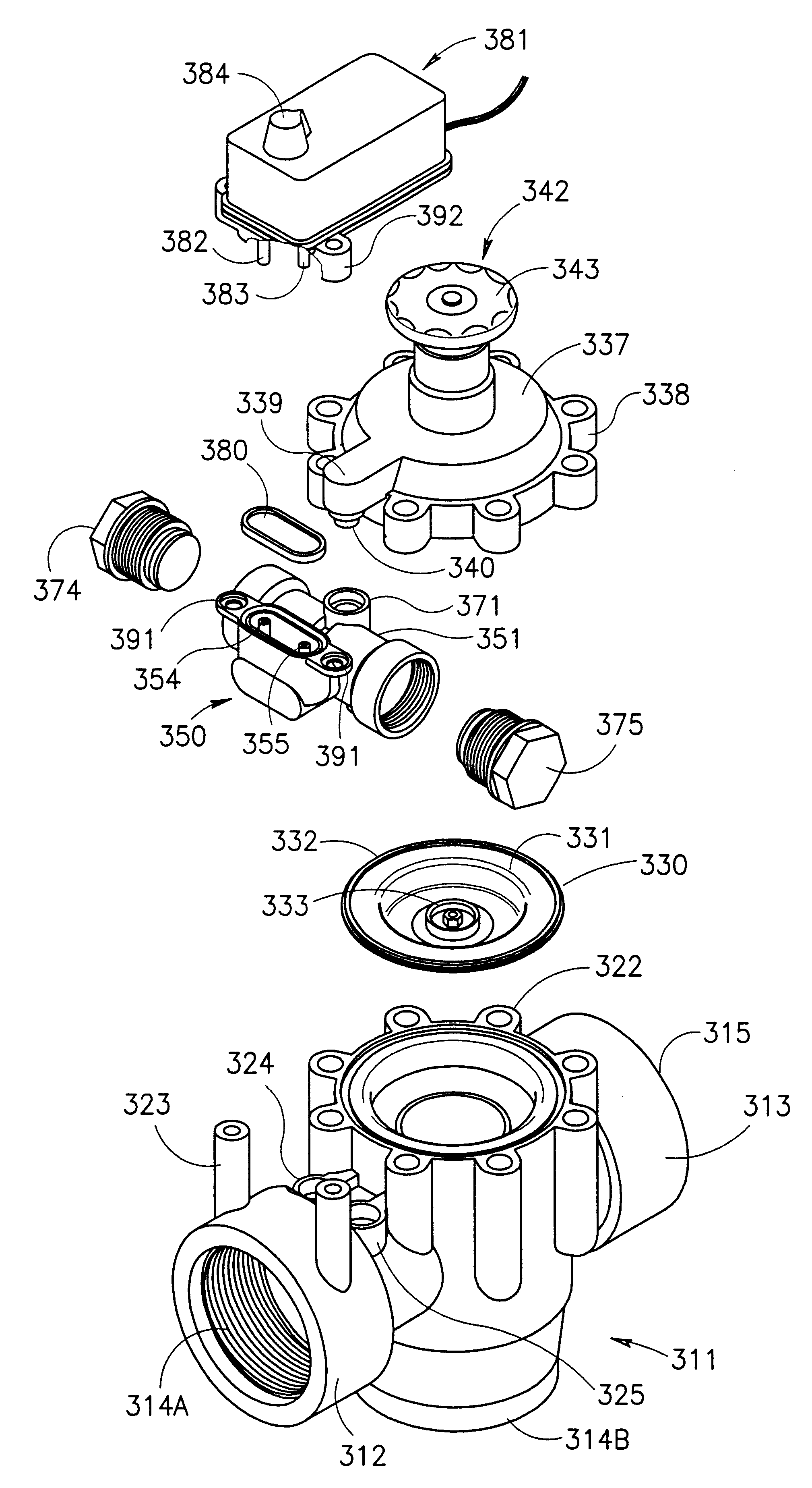
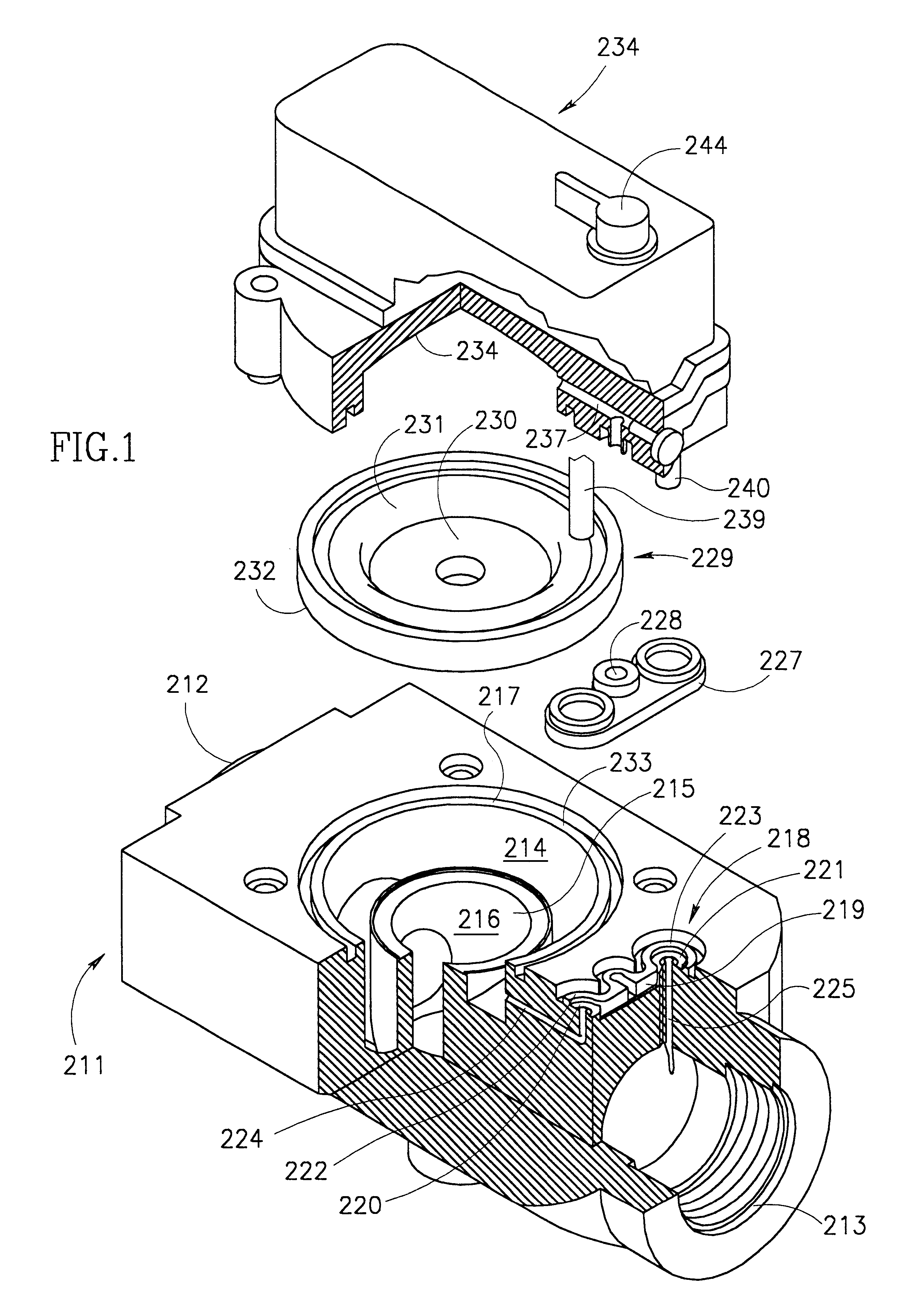
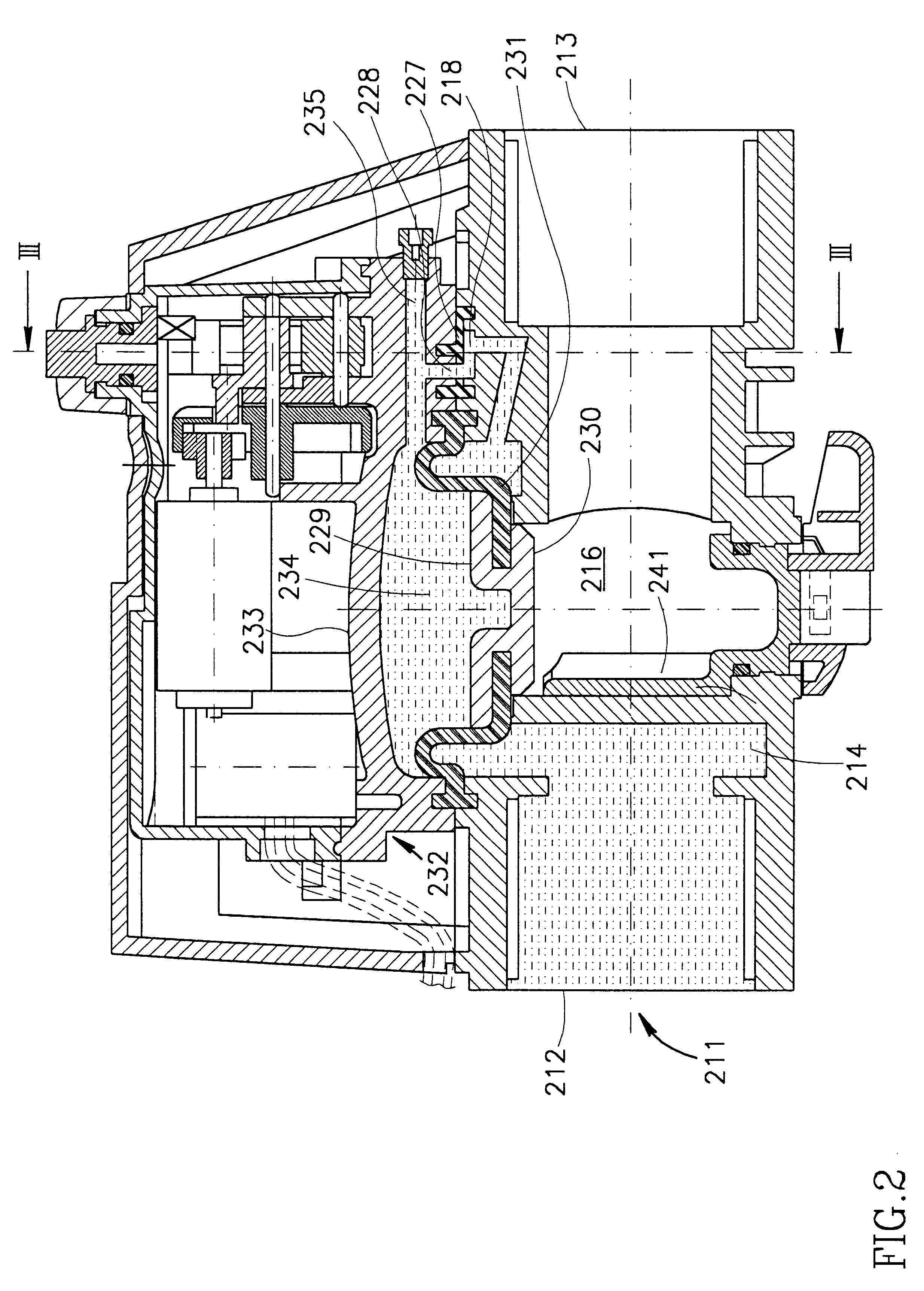
Reference will now be made to FIGS. 1 to 5 of the drawings for a detailed description of an electrically operated hydraulic valve in accordance with the present invention.

The valve comprises an elongated valve housing block 211 constituting a first housing component which is formed at one end thereof with a liquid inlet port 212 and at the opposite end thereof, with a liquid outlet port 213.

Formed in a central position of the housing block 211 is a substantially cylindrical inlet chamber 214 of essentially annular cross-sectional shape which communicates with the liquid inlet port 212.

Formed within the inlet chamber 214 and separated therefrom by a cylindrical wall 215 is a centrally disposed outlet chamber 216, substantially coaxial with the inlet chamber 214 and which communicates with the liquid outlet port 213. An upper edge of the cylindrical wall 215 constitutes diaphragm valve seating 217.

The hydraulic valve is furthermore provided with a command valve which comprises a comma...

second embodiment

FIG. 21 illustrates the switching circuitry 530 wherein additional components are included in order to prevent such an occurrence. The switching circuit shown in FIG. 21 is substantially identical to that described above with reference in FIG. 20 with the sole exception of the provision of a secondary charge PNP 532 connected across the motor 521 and comprising a resistor 534 in series with diode 536.

When the bridge rectifier 502 is connected to a source of a.c. power, the resulting rectified d.c. voltage across the positive and negative supply rails 504 and 506 renders the transistor 510 open circuit, whilst allowing current to flow through the diode 518 and the motor 526 in series with the capacitor 528 as well as through the secondary charge path 532 and the capacitor 528. Thus, the secondary charge path 532 acts as a bi-path for ensuring that more current flows through the capacitor 528 than flows through the motor 526. By such means, it may be arranged that the capacitor 528 ch...


PUM


Abstract

A hydraulic diaphragm valve comprising a housing, an inlet, an outlet, a diaphragm valve seating between the inlet and the outlet, a sealing diaphragm mounted in the housing and displaceable about the diaphragm valve seating, so as to close and open a flow path between the inlet and outlet, a valve control chamber and a command valve comprising a first duct communicating a one end thereof with the valve inlet, and at an opposite end thereof with a first command valve seating, a second duct communicating into one end with the valve outlet, and at an opposite end thereof, with a second command valve seating. A third duct communicates at one end with the valve control chamber and at its opposite end it selectively communicates with the first and second command valve seatings. A flexible command diaphragm is selectively biased into sealing engagement with one or other of the command valve seatings to effect communication between the third duct and the command valve seating not in seating engagement with the command diaphragm.

Description

FIELD AND BACKGROUND OF THE INVENTIONThis present invention is generally in the field of an electrically controlled hydraulic diaphragm valve and it is connected also with a flow command valve therefor. The invention is also concerned with other compounds of the diaphragm valve and its control.Electrical valves of the aforementioned type are used in a variety of applications in which it is desired to control flow through a hydraulic supply line.In diaphragm valves, the diaphragm itself is disposed between a fluid inlet of the valve's housing and the valve's outlet. There is provided a closure member having a surface area greater than that of the inlet passage. The valve is closed by forcing the closure member against the diaphragm so as to distort the diaphragm onto the fluid inlet, thereby sealing the valve. If the closure member is operated via an electric motor, then one way to apply sufficient force to the closure member would be to employ a correspondingly powerful motor. Howev...

Claims


Application Information

Patent Timeline
IPC IPC(8): F16K31/36F16K31/40
CPCF16K31/402Y10T137/7761Y10T137/7764
Inventor ZAKAI, AVIKATZMAN, YOUVALRYABTSEV, VLADIMIR
Owner NETAFIM LTD
Why Eureka
Try Eureka