
Method for measuring the intra-ocular pressure through the eyelid and device for realizing the same

a technology of intraocular pressure and eyelid, which is applied in the field of measuring the intraocular pressure through the eyelid and the device for realizing the same, can solve the problems of not providing stable reliable interaction of the device with an eye, and not providing the rigidity of the connection of the supporting portion with an eye. , to achieve the effect of increasing the rigidity of the connection of the supporting portion and increasing the accuracy of the measuremen

Inactive Publication Date: 2002-05-28
GENNADY KONSTANTINOVICH PILETABKY
View PDF3 Cites 14 Cited by
  • Summary
  • Abstract
  • Description
  • Claims
  • Application Information

AI Technical Summary

Benefits of technology

The technical result at which the proposal is aimed consists in increasing of accuracy of measurement of IOP by means of eliminating the influence of shock-absorption of an eyelid and by means of increasing the rigidity of the connection of the supporting portion with the eye because of static eyelid deformation by the support weight while measuring IOP in the gristle region.
Additionally there is provided stability of maintenance of the distance between the eyelid surface, on which dynamic deformation of an eye is realized, and the rod base in its initial position.
Advantageously the method includes realizing additional static deformation of the eyelid section, on which dynamic deformation of an eye is realized, by subjecting to applanation of the surface of this section parallel to the base plane of the freely falling body by means of pressing the edges of this eyelid section to the eyeball, providing constant distance between its surface and the base of the freely falling body in its initial position.
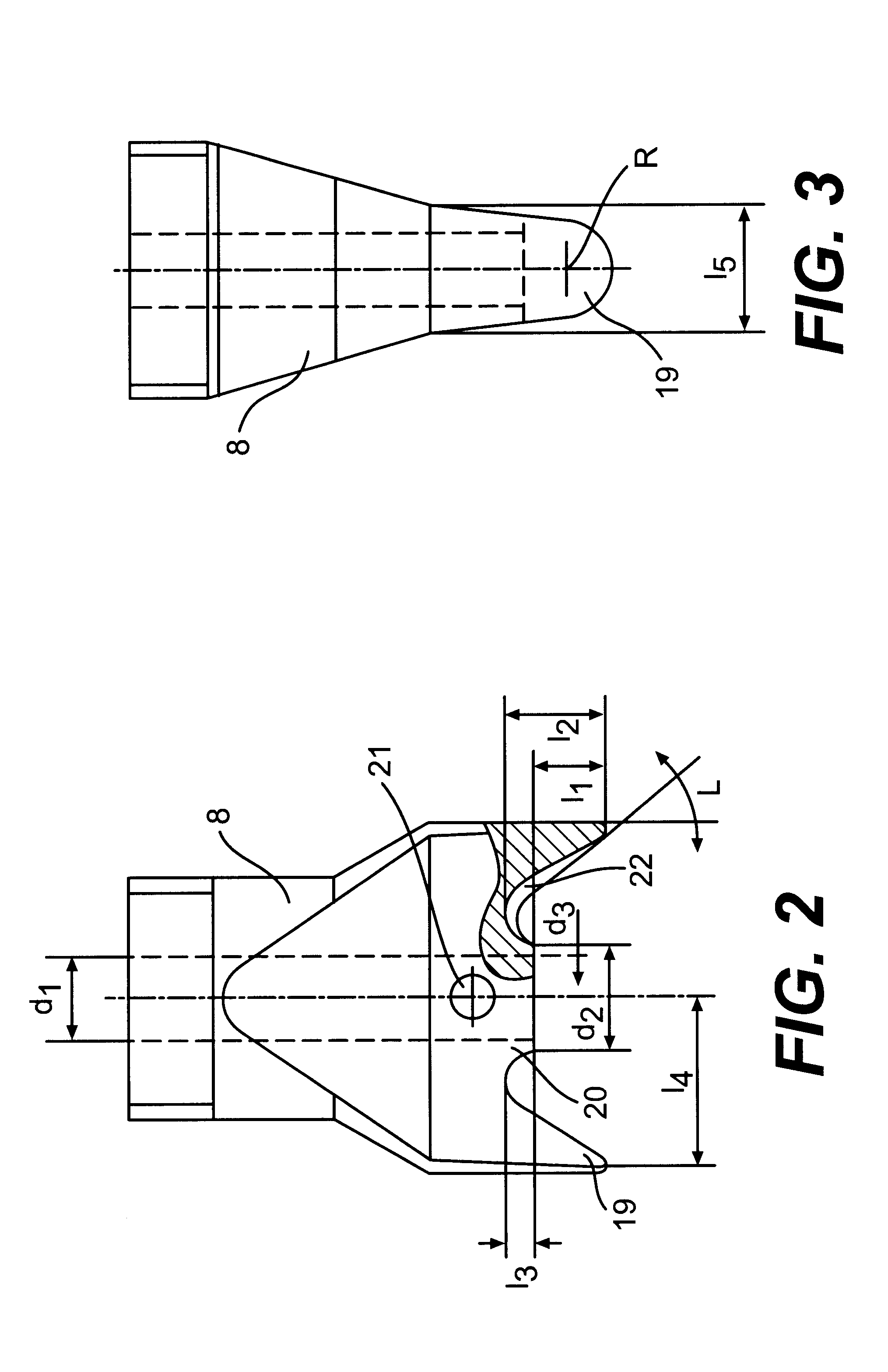
Advantageously, confronting working surfaces of the projections of the supporting part of the bushing, have concave form. Preferably, the supporting part of the bushing has a member for applanation of an eyelid section surface, contacting with the freely falling body during striking loading, parallel to the base surface of the later for providing constant distance between the eyelid section surface and the base of the freely falling body in the initial position.
Using of the supporting portion with projections with small base area permits the increase of loading of the support on the eyelid in their setting places, providing pressing of the eyelid to eliminate its shock-absorption, and to provide rigid connection of the supporting portion of the device with the eye during measurement.
Besides placing the support projections on the eyelid in the gristle region eliminates eye deformation under the projections.

Problems solved by technology

Using of an annular support does not eliminate eyelid shock-absorption in places of interacting of the support with an eye through eyelid and does not provide stable reliable interaction of the device with an eye during measurement.
The eyelid deformation by the annular supporting part of the tonometer does not eliminate shock-absorption of an eyelid in the setting place.
Besides the rigidity of the connection of the support with an eye is not provided in this tonometer.
However the annular supporting part does not provide the rigidity of the connection of the device with the eyelid-covered eye and does not eliminate shock-absorption of an eyelid.
Thus in all the known devices deformation of an eyelid by the annular supporting portion does not eliminate the influence of the shock-absorption features of an eyelid, which decreases the accuracy of measurement of IOP.
Besides large area of the annular support does not permit to place it on small gristle section of an eyelid.

Method used


Image

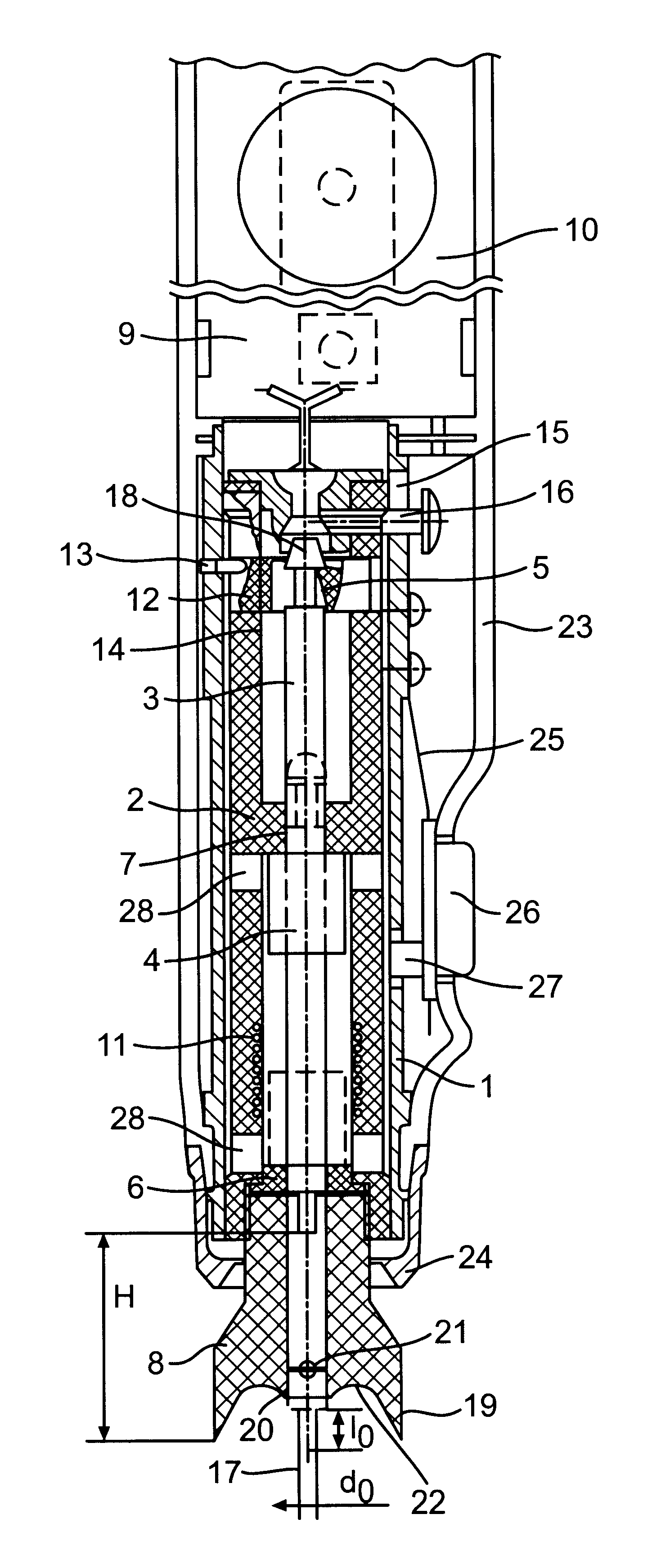
  • Method for measuring the intra-ocular pressure through the eyelid and device for realizing the same
  • Method for measuring the intra-ocular pressure through the eyelid and device for realizing the same
  • Method for measuring the intra-ocular pressure through the eyelid and device for realizing the same

Examples


Embodiment Construction

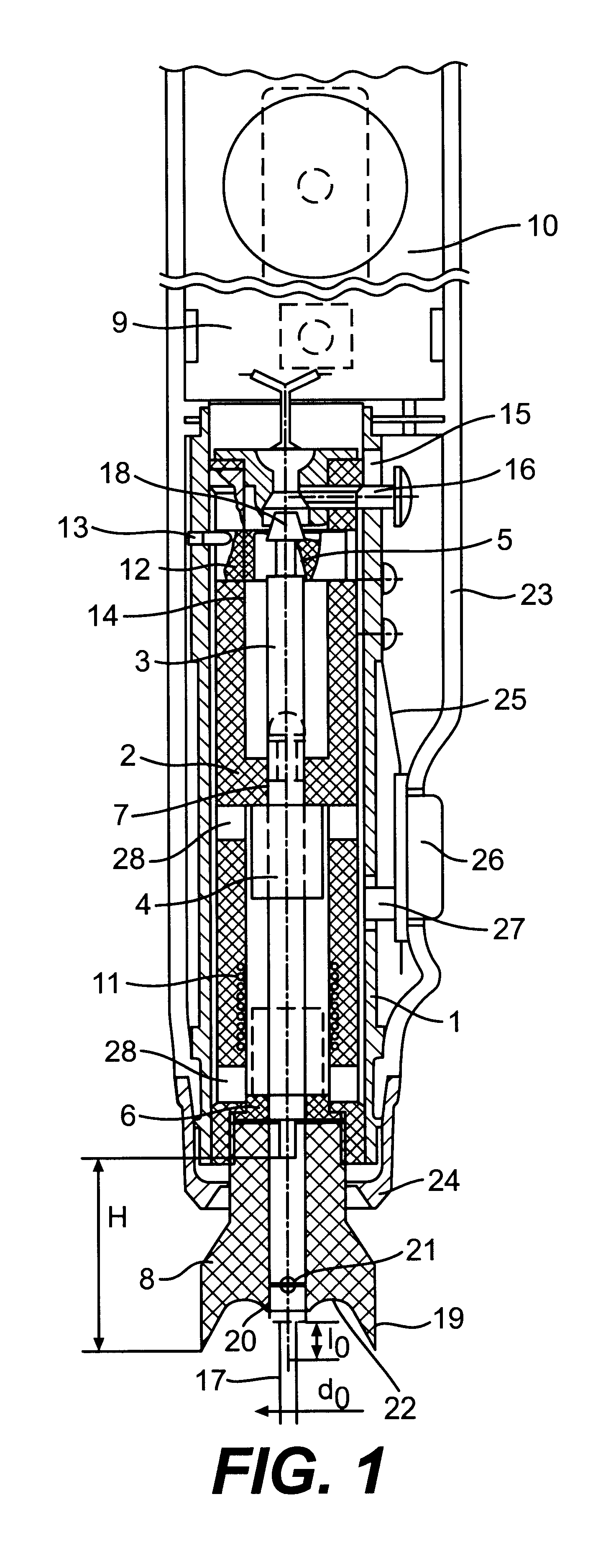
Measuring intraocular pressure with the help of the proposed device is carried out in following manner: the device is placed on the patient's eyelid in vertical position (FIG. 6), acting upon an eye through an eyelid in its gristle region (FIG. 4) by two wedge-shaped projections set in two points (A and B), located at equal distances 7-10 mm from the displacement axis of the falling body parallel with the horizontal eye meridian and symmetrically from the axis, passing through the eye center (FIG. 5) for providing rigid connection of the device support with an eye.

Acting upon an eyelid-covered eye by the support projections with small base area in the gristle region eliminates eyelid shock-absorption. During measuring IOP (FIG. 6) dynamic deformation of an eyelid and an eyeball (in a sclera or cornea region depending upon preliminary set patient's visual angle) realized with a freely falling body in the form of a rod, by time function of which displacement they judge about IOP.

A dev...


PUM


Abstract

A method of measuring intraocular pressure through an eyelid includes the step of subjecting the gristle region of an opened eyelid to two spaced contacts providing static support loading that deforms the eyelid. Simultaneously, the gristle region of the eyelid is subjected to the dynamic deformation of a body falling freely relative to the support contacts, such dynamic deformation being transferred to an eyeball area below the eyelid. The spaced contacts are located at equal distances from an axis of displacement of the freely falling body, thereby providing a decrease of eyeball shock absorption under the support. The amount of resilient deformation of a surface of the eyeball is then determined.

Description

The proposal relates to medicine, and particularly to ophthalmology, and it may be used for measuring intraocular pressure (IOP) through the eyelid both in the cornea region, and in the sclerotic region of an eye by means of express method during mass examination of population on glaucoma, during checking of the correctness of its treatment and during individual control of intraocular pressure without eye anesthetization.A method of measuring intraocular pressure is known, comprising static deformation of an eye by means of the weight of a support with annular supporting part and dynamic deformation of an eye cornea through eyelid by means of a ball freely falling from the height 120-150 mm with the weight 0.3-0.7 g and further determining of the amount of pressure by the first ball rebound (RU 2007951, Cl. A 61 B 3 / 16, 29.06.90).In the above method measurement accuracy depends greatly upon individual eyelid structure and features (eyelid thickness, resilience etc.).The square of in...

Claims


Application Information

Patent Timeline
IPC IPC(8): A61B3/16
CPCA61B3/16
Inventor PILETSKY, GENNADY KONSTANTINOVICHZELENJUK, JURY IOSIFOVICHIVANISCHEV, KONSTANTIN VASILIEVICHNESTEROV, ARKADY PAVLOVICHPESKOV, NIKOLAI EVGENIEVICHPILETSKY, NIKOLAI GENNADIEVICHSTROEV, EVGENY ALEXEEVICHCHERVYAKOV, ALEXANDR NIKOLAEVICH
Owner GENNADY KONSTANTINOVICH PILETABKY
Learn More