Apparatus and method for delivering and deploying an expandable body member in a uterine cavity

a technology of expandable body parts and abdominal cavity, which is applied in the field of abdominal cavity delivery and uterine cavity abdominal cavity apparatus, can solve the problems that the expansion of the body member to its expanded state might not adequately expand the uterine cavity, and the contact between the endometrial layer and the surface of the expandable body member might be insufficient, so as to achieve the effect of relieving fluid pressur

Inactive Publication Date: 2002-05-28
YOON INBAE +1
View PDF22 Cites 144 Cited by
  • Summary
  • Abstract
  • Description
  • Claims
  • Application Information

AI Technical Summary

Benefits of technology

It is another object of the invention to provide an apparatus and method for delivering an expandable body member into the uterine cavity of the uterus and deploying the expandable body member in the uterine cavity such that contact between the endometrial layer and an expanded body member surface of the expandable body member in the expanded state is maximized.
Accordingly, an apparatus and method for delivering an expandable body member into a uterine cavity and deploying the expandable body member from its compressed state to its expanded state are hereinafter described. The apparatus of the invention delivers the expandable body member in a compressed state through the cervical opening and into the uterine cavity of a living body and deploys the expandable body member from the compressed state to the expanded state while the expandable body member is disposed in the uterine cavity. The apparatus includes an elongated tubular member and a fluid-providing device. The elongated tubular member has a distal portion, a proximal portion and an intermediate portion disposed between the distal portion and the proximal portion. The expandable body member is connected to the distal portion. The fluid-providing device is connected to the proximal portion of the elongated tubular member. The fluid-providing device is operative to provide a fluid to the uterine cavity through the elongated tubular member at a sufficient pressure to inflate the uterine cavity to a volume larger than the expandable body member in the expanded state. The provided fluid also causes the expandable body member to expand from the compressed state to the expanded state.
The method of the invention delivers the expandable body member into the uterine cavity of the uterus through a cervical opening and deploys the expandable body member in the uterine cavity which is defined by the endometrial layer. The expandable body member expands from a compressed state to an expanded state to form an expanded body member surface. One step of the method of the present invention is inserting the expandable body member in the compressed state through the cervical opening and into the uterine cavity. Another step provides a fluid to the uterine cavity at a pressure sufficient to inflate the uterine cavity. Another step causes the expandable body member to expand from the compressed state to the expanded state. Another step relieves the fluid pressure thereby allowing the uterine cavity to collapse about the expandable body member in the expanded state so that the endometrial layer and the expanded body surface substantially contact each other in a facially opposing relationship.

Problems solved by technology

Particularly, with ablation devices using expandable body members such as the ones described above, expansion of the body member to its expanded state might not adequately expand the uterine cavity.
Thus, contact between the endometrial layer and the surface of the expandable body member might be insufficient.

Method used


Image

  • Apparatus and method for delivering and deploying an expandable body member in a uterine cavity
  • Apparatus and method for delivering and deploying an expandable body member in a uterine cavity
  • Apparatus and method for delivering and deploying an expandable body member in a uterine cavity

Examples


Embodiment Construction

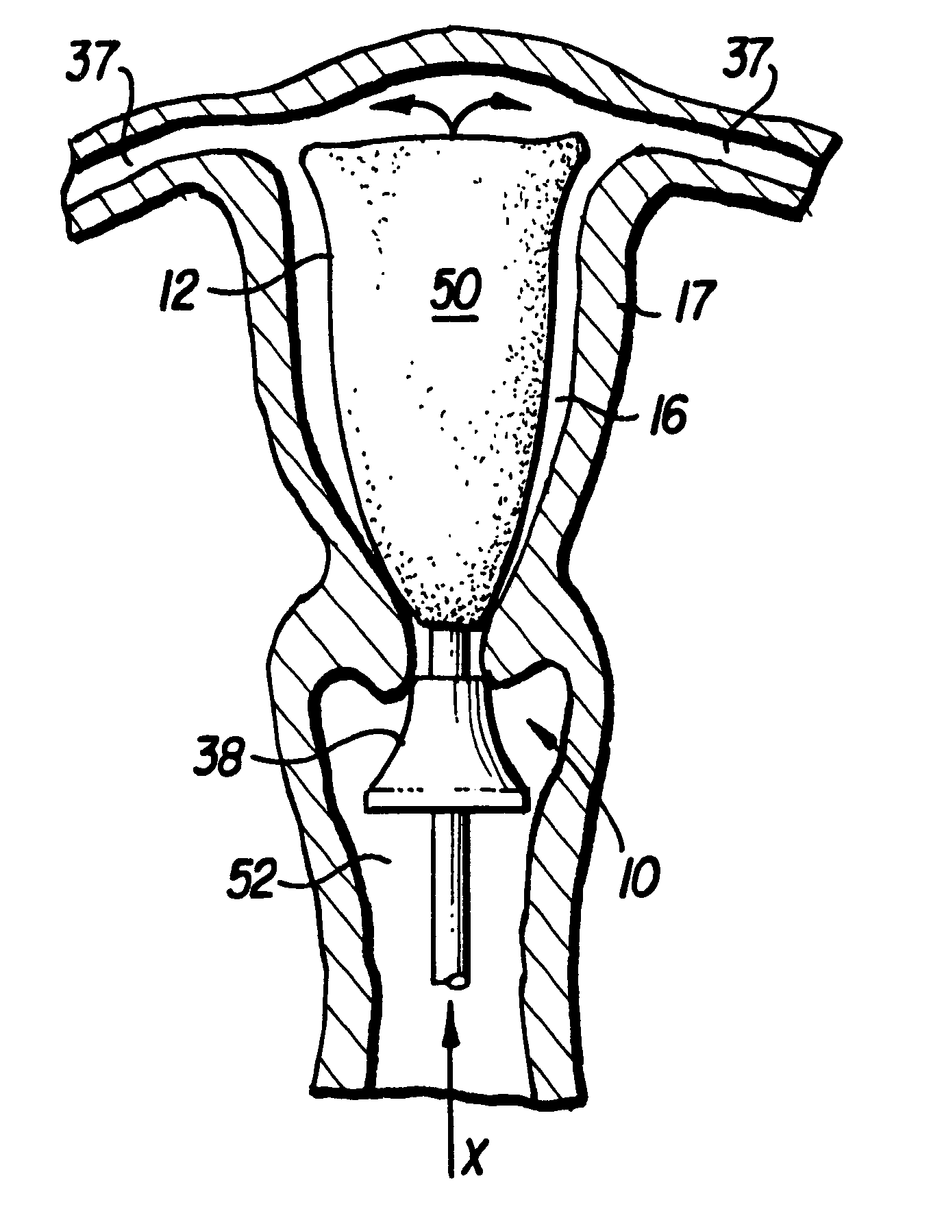
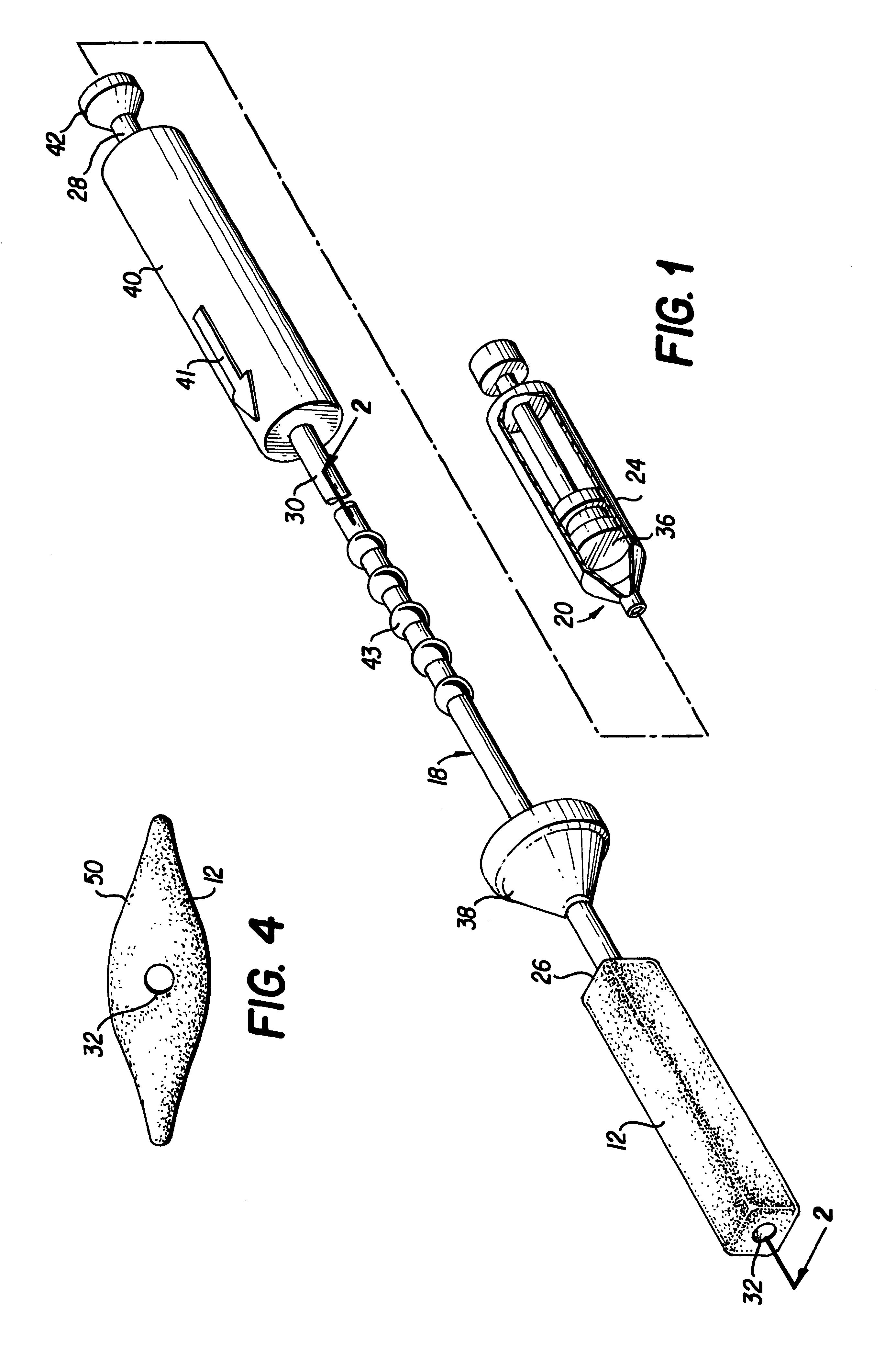
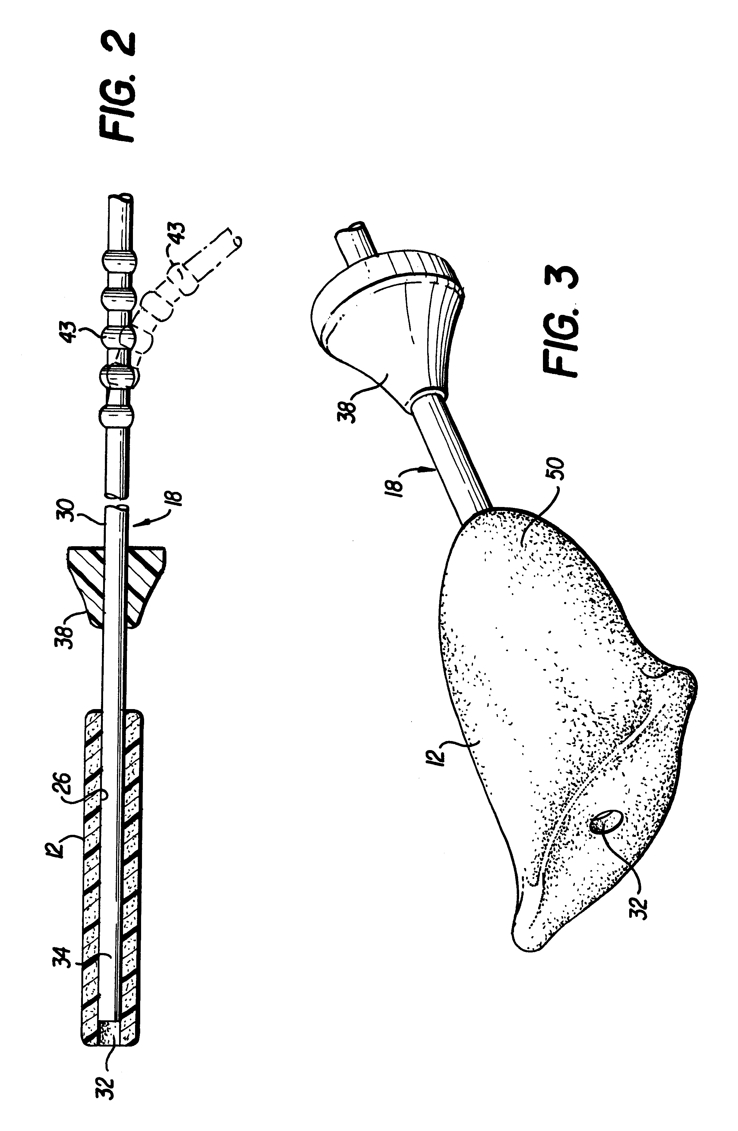
An apparatus 10 of the present invention is generally introduced in FIGS. 1-4. As illustrated in FIGS. 5A-11B, the apparatus 10 of the present invention delivers an expandable body member 12 in a compressed state (FIGS. 1 and 2) through a cervical opening 14 and into a uterine cavity 16 of a uterus 17 of a living body. The apparatus 10 of the present invention also deploys the expandable body member 12 from the compressed state to an expanded state (FIGS. 3 and 4) while the expandable body member 12 is disposed in the uterine cavity 16 (FIGS. 7A-11B). As best shown in FIG. 1, the apparatus 10 of the present invention includes an elongated tubular member 18 and a fluid-providing device 20. Although not be way of limitation, the fluid-providing device 20 is illustrated as syringe assembly that includes a syringe 24.

The elongated tubular member 18 has a distal portion 26 as best shown in FIG. 2, a proximal portion 28 and an intermediate portion 30 which is disposed between the distal p...


PUM


Abstract

An apparatus and method delivers an expandable body member into a uterine cavity of a uterus through a cervical opening and deploys the expandable body member in the uterine cavity. The expandable body member in a compressed state is inserted into the uterine cavity. A fluid is provided to the uterine cavity at a pressure sufficient to inflate the uterine cavity. The expandable body member expands from the compressed state to the expanded state. After expansion of the expandable body member and inflation of the uterine cavity, the fluid pressure is relieved thereby collapsing the uterine cavity about the expandable body member in the expanded state such that an endometrial layer of the uterus and a surface of the expandable body member substantially contact each other in a facially opposing relationship maximizing contact therebetween. The apparatus which performs the method includes an elongated tubular member having the expandable body member connected to a distal portion of the elongated tubular member and a fluid-providing device connected to a proximal portion of the elongated tubular member.

Description

The present invention relates to an apparatus and method for delivering and deploying an expandable body member in a uterine cavity. More particularly, the present invention is directed to an apparatus and method for delivering and deploying an expandable body member in the uterine cavity so that contact of the endometrial layer in the uterine cavity and the surface of the expandable body member in an expanded state is maximized.Ablation is a medical procedure which may be performed to treat one of many conditions such as abnormal bleeding of the endometrial layer of the uterus. To perform an ablation procedure, many types of ablation devices have been developed.U.S. Pat. No. 5,769,880 to Truckai et al. teaches an apparatus and method for performing ablation of organs. The ablation apparatus includes an electrode carrying member that is mounted to a distal end of an elongated shaft. An array of electrodes is mounted to the surface of the electrode carrying member. After placement of...

Claims


Application Information

Patent Timeline
Patent Type & Authority Patents(United States)
IPC IPC(8): A61B17/42A61M13/00A61B17/00A61M29/02A61B17/12A61M25/10A61F2/958
CPCA61B17/00234A61B17/12099A61B17/1219A61B17/42A61M13/003A61M29/02A61B17/12022A61M2210/1433A61B2017/4216A61M25/1011A61M2025/1052A61B2017/1205
Inventor YOON, INBAEBRINKERHOFF, RONALD J.KATZ, HAL H.KRAIMER, WILLIAM J.NOLAN, LEO J.
Owner YOON INBAE
Why Eureka
Try Eureka