Thermally actuated control device

a control device and thermal actuator technology, applied in the direction of machines/engines, mechanical devices, contacts, etc., can solve the problems of high operating energy requirements and mechanical devices that cannot compete with each other

Inactive Publication Date: 2002-05-28
LEVINGARD TECH
View PDF33 Cites 13 Cited by
  • Summary
  • Abstract
  • Description
  • Claims
  • Application Information

AI Technical Summary

Benefits of technology

It is yet another object of the present invention to provide a thermal energy operated micro-miniature me...

Problems solved by technology

Mechanical devices could no longer compete because of their inh...

Method used


Image

  • Thermally actuated control device
  • Thermally actuated control device
  • Thermally actuated control device

Examples


Embodiment Construction

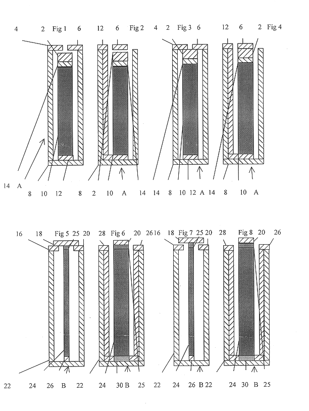
Referring now to FIG. 1 an energy controller (device A) is shown with a body portion 8 made of a thermal insulating material. At the upper end a pair of conductor members 4 & 6 are mounted on the insulator body 8. Mounted within thermal insulating body 8 is thermal expander / contracter member 10. Mounted on top of expander member 10 is bridging member 2. Bridging member 2 is separated from direct contact with expander / contractor 10 by insulator 14 which may also serve as a shock absorber. Bridge insulator 14 stops current from flowing from the input and output to the expander / contracter 10. Thermal connection to expander / contracter 10 is made by thermal conductor 12 which brings the thermal energy to and from the expander / contracter 10.

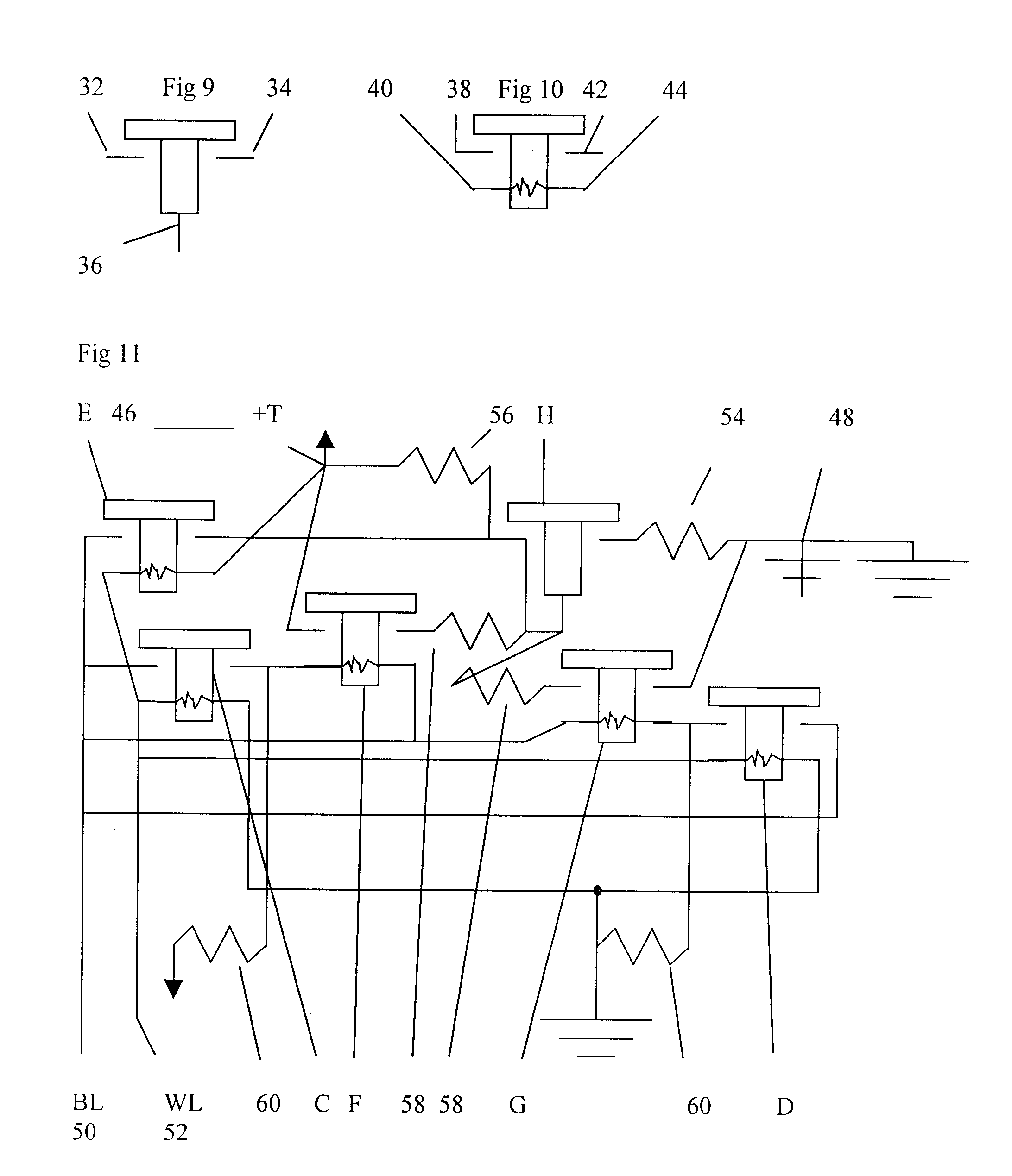
The term "expander / contracter" is used to denote the element that physically moves a bridging member into and out of operative relationship with an energy transmission path. The term "bridging member" is used to denote the third conductor element that ...


PUM


Abstract

A micro miniature solid state mechanical switch device operated by thermal energy for the control of thermal and electrical energy is shown. A gap in an energy path is bridged by an energy conductor that is mechanically moved into and out of operative position with the gap in the energy path.

Description

BACKGROUND OF INVENTIONThis invention relates to solid state devices for controlling the flow of energy and more particularly to control devices, operated by application of thermal energy, which physically move energy transmission elements in and out of an energy flow path to selectively control the flow of energy along said path.For the last several decades devices for controlling the flow of energy and operation of machines have typically consisted of electronic devices such as the transistor and related solid state components which have resulted in a multitude of high speed, small size and low power drain devices previously unknown. Mechanical devices could no longer compete because of their inherent large size, slow speed, and high operating energy requirements.OBJECTS AND SUMMARY OF INVENTIONAccordingly it is an object of the present invention to provide a mechanically operated solid state device that overcomes the limitations of the prior art.It is another object of the presen...

Claims


Application Information

Patent Timeline
IPC IPC(8): H01H1/00H01H37/48H01H37/00
CPCH01H1/0036H01H2037/008H01H37/48
Inventor ROSS, STEVEN J.
Owner LEVINGARD TECH
Why Eureka
Try Eureka