Arrangement for the central monitoring and/or control of at least one apparatus

a central monitoring and/or control technology, applied in the direction of electric programme control, program control, instruments, etc., can solve the problems of increasing the expenditure for the central control on the device side, comparatively difficult to log in or out of a unit during operation, and the limitation of the total number of units which can be controlled by the master computer

Inactive Publication Date: 2002-05-28
KARL STORZ ENDOSCOPY AMERICA
View PDF15 Cites 94 Cited by
  • Summary
  • Abstract
  • Description
  • Claims
  • Application Information

AI Technical Summary

Problems solved by technology

The use of serial or parallel interfaces for controlling the devices presents the disadvantage that the number of the total of units which can be controlled by the master computer is restricted by the number of computer interfaces.
Networking, on the other hand, requires the application of "comparatively intelligent" units so that the expenditure is increased for the central control on the device side.
Moreover, in standard networks, which are implemented, for instance, on the basis of network operating systems such as Novell, it is comparatively difficult to log in or off a unit during operation.
Apart therefrom, the known network solutions are not fail-safe to such a high degree that they could be employed in the operating theatre.
But even if only a comparatively small number of units is centrally controlled the following problem always occurs whenever more than one unit is controlled:
In such a situation the operator resets the operating parameters for this unit unintentionally.
But even if this error is noticed immediately it is frequently difficult to "reset" the operating parameters again to "reasonable" values.
With these provisions the problem is solved that in case of application of a central controller unintentionally the "wrong unit" is operated and thus reset.

Method used


Image

  • Arrangement for the central monitoring and/or control of at least one apparatus
  • Arrangement for the central monitoring and/or control of at least one apparatus
  • Arrangement for the central monitoring and/or control of at least one apparatus

Examples


Embodiment Construction

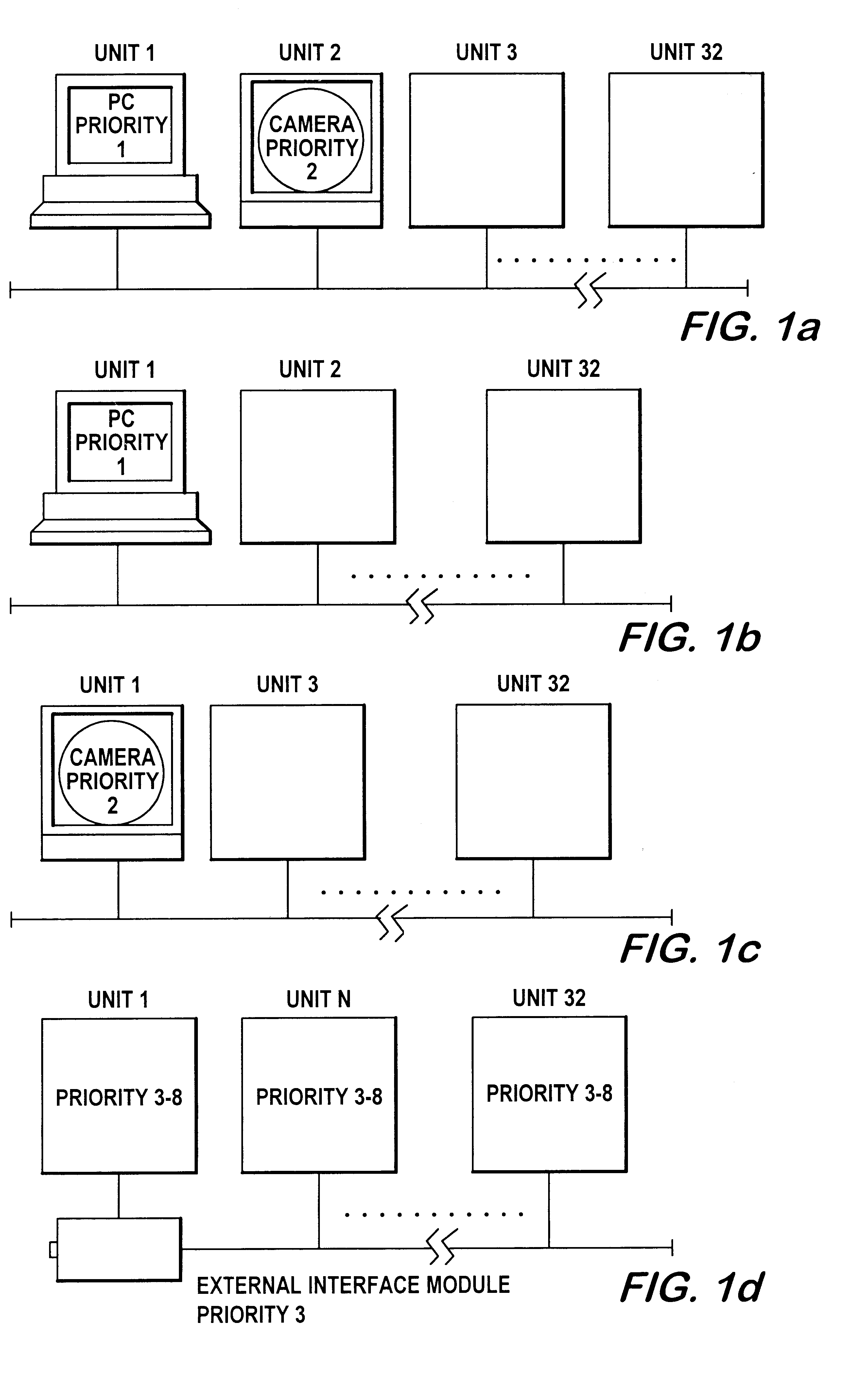
FIG. 1 shows various possible configurations of the network used in accordance with the present invention.

FIG. 1a shows as first possibility the case where a master computer PC (unit 1) serves as network master whereas a camera controller or a video signal processor (unit 2), respectively, is used as monitor. The units 3 to 32, e.g. insufflators, pumps, HF surgical equipment, light sources, etc., are connected as network slaves.

FIG. 1b illustrates as second possibility the case where a master computer PC (unit 1) is used as network master and monitor whereas all other units 2 to 32 are connected as network slaves.

FIG. 1c eventually shows as third possibility the case where the camera controller (unit 1) is used as both network master and monitor whereas all other units 2 to 32 are again connected as network slaves,

FIG. 1d is a view of the case that an external interface module is connected as network master, without the provision of a monitor. The units 1 to 32 are connected as netw...


PUM


Abstract

What is described here is a system for centrally monitoring and/or controlling at least one unit for endoscopy and particularly for minimally invasive surgery, such as an insufflation means, a pump, a light source and/or a video camera, wherein the unit or units to be controlled are interconnected via interfaces.The inventive system is characterised by the combination of the following features:the units are connected via the interfaces on a self-configuring bus to a BUS master,the BUS master configures the bus automatically,the BUS master monitors the communication on the bus for correct execution.

Description

The present invention relates to a system for centrally monitoring and / or controlling at least one unit for endoscopy, and specifically for minimal invasive surgery, in accordance with the introductory clause of Patent claim 1.PRIOR ARTSystems for centrally monitoring and / or controlling endoscopic units are known, for instance, from the European Patent EP 0 319 762 A1 or the German Patent DE 37 41 833 C1 of the same priority, the U.S. Pat. No. 5,627,584, the international patent WO 95 / 22363, the Japanese Patent A 62-46182 or the German Utility Model U1 92 18 373. Explicit reference is made to these prior art documents as far as all other details are concerned which are not explained here in all their details.The known systems of the type which the introductory clause of Patent claim 1 starts out from may be employed, for instance, for controlling one or several insufflation units, pumps, an illuminating device for the image field of an endoscope, an HF instrument for cutting or coag...

Claims


Application Information

Patent Timeline
Patent Type & Authority Patents(United States)
IPC IPC(8): G05B23/02G05B19/042G05B19/04A61B17/00
CPCG05B19/0423A61B17/00234G05B2219/45169G05B2219/25056G05B2219/25084G05B2219/25032
Inventor CHATENEVER, DAVIDIRION, KLAUSNOVAK, PAVELHILZINGER, HANS-UWE
Owner KARL STORZ ENDOSCOPY AMERICA
Why Eureka
Try Eureka