Control apparatus for hydraulically-operated vehicular transmission

a control apparatus and hydraulic operation technology, applied in the direction of gearing control, gearing element, belt/chain/gearing, etc., can solve the problem that the decrease in the oil pressure in the hydraulic engaging element for the first speed transmission train cannot be effectively buffered, the speed change response to the skipped speed change command becomes poor, and the speed change shock and the poor speed change respons

Inactive Publication Date: 2002-06-04
HONDA MOTOR CO LTD
View PDF5 Cites 9 Cited by
  • Summary
  • Abstract
  • Description
  • Claims
  • Application Information

AI Technical Summary

Problems solved by technology

As a result, the speed change response to the skipped speed change command becomes poor.
However, the pressure decrease characteristics of the hydraulic engaging element for the first speed transmission train will be subject to an effect by the accumulator.
Therefore, the accumulator will be a possible cause for external perturbations in the pressu...

Method used


Image

  • Control apparatus for hydraulically-operated vehicular transmission
  • Control apparatus for hydraulically-operated vehicular transmission
  • Control apparatus for hydraulically-operated vehicular transmission

Examples


Embodiment Construction

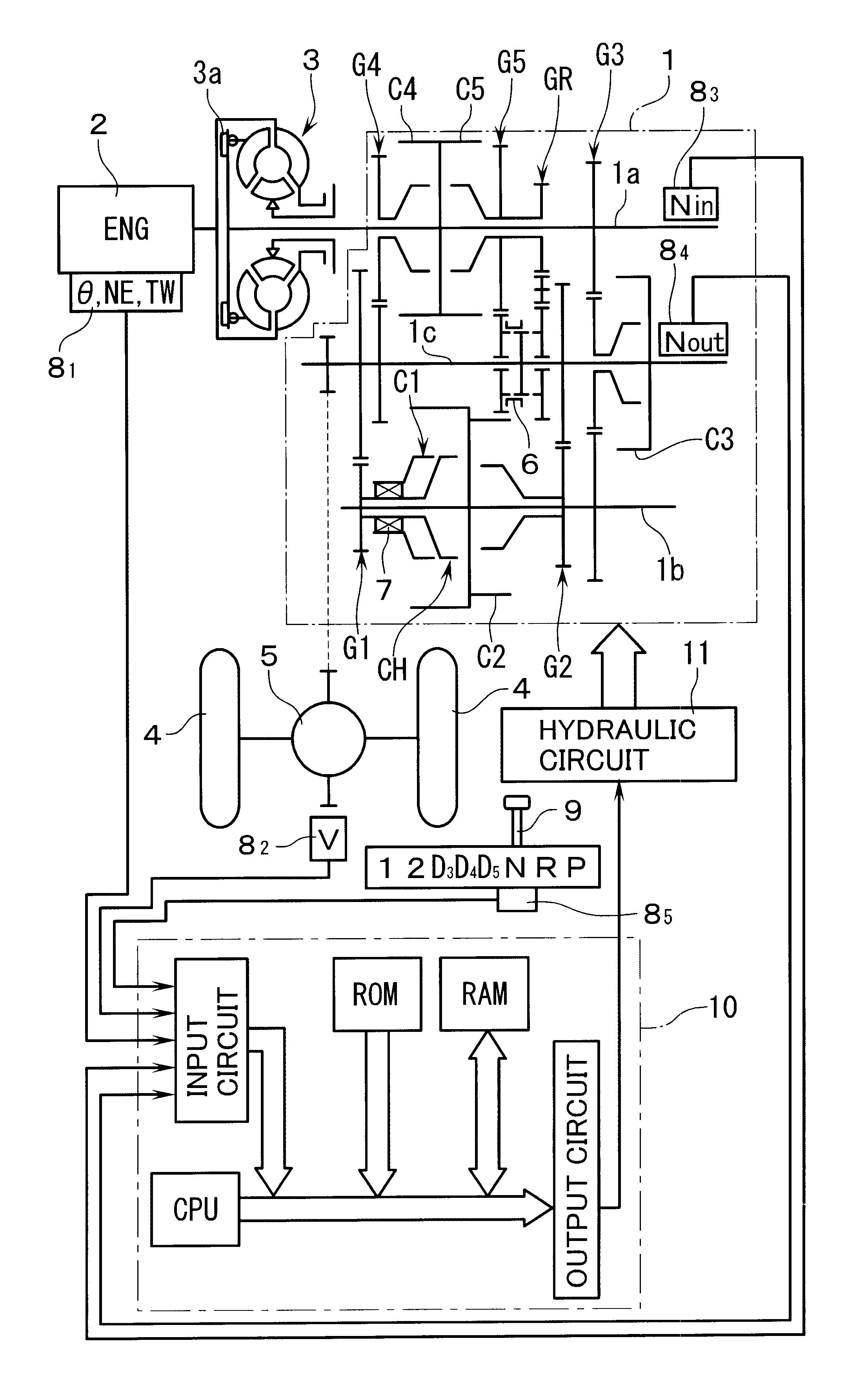
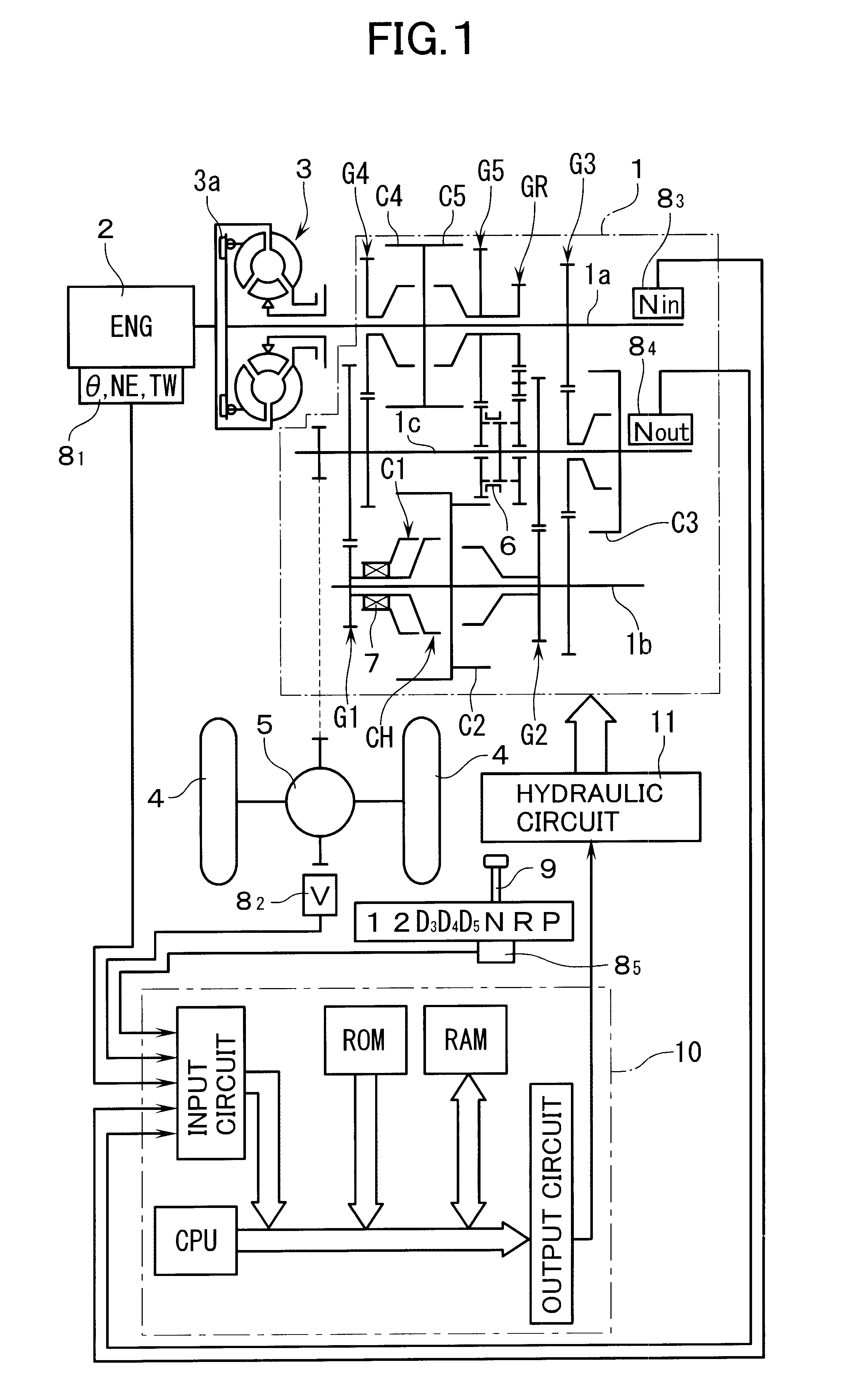
With reference to FIG. 1, reference numeral 1 denotes a hydraulically-operated vehicular transmission for providing speed changing of five forward transmission trains and one reverse transmission train. The transmission 1 is provided with a first input shaft 1a which is connected to an engine 2 through a fluid torque converter 3 which is equipped with a lock-up clutch 3a; a second input shaft 1b which rotates synchronously with the first input shaft 1a; and an output shaft 1c which is connected to driving wheels 4 of a vehicle through a differential gear 5. Between the second input shaft 1b and the output shaft 1c, there are disposed in parallel with each other a 1st speed transmission train G1 and a 2nd-speed transmission train G2 for forward running. Between the first input shaft 1a and the output shaft 1c, there are disposed in parallel with each other 3rd-speed through 5th-speed transmission trains G3, G4, G5 and a reverse transmission train GR. 1st-speed through 5th-speed hydra...


PUM


Abstract

Shift valves 141, 142, 143 are provided to switch oil passage connections to a state in which an oil pressure in one hydraulic clutch of an arbitrary speed transmission train and an oil pressure in a hydraulic clutch of a transmission train which is adjacent thereto as seen in the order of speed are controllable by a pair of linear solenoid valves 201, 202. Skipped speed change from a predetermined first speed transmission train to a second speed transmission train which is not adjacent to the first speed transmission train is made possible. In concrete, a large-capacity accumulator A5 is connected to an oil passage L19 which is in communication with 5th-speed hydraulic clutch C5. At the time of skipped speed changing from 5th speed to 3rd speed, shift valves 141, 142, 143 are switched to a state of 3rd-4th speed change. The oil pressures in the hydraulic clutches C3, C4 for 3rd and 4th speed transmission trains, respectively, are made controllable by the linear solenoid valves 201, 202. While buffering the pressure decrease of the oil pressure in the 5th-speed hydraulic clutch C5 by the accumulator A5, pressure increase control of 3rd-speed clutch C3 is carried out by one of the linear solenoid valves to thereby skip-downshift from 5th to 3rd speed. The other linear solenoid valve is held at a low-pressure waiting state to prepare itself for the 3rd-4th speed switch-upshifting.

Description

1. Field of the InventionThe present invention relates to a control apparatus for a hydraulically-operated vehicular transmission having a plurality of hydraulic engaging elements for selectively establishing a plurality of speed transmission trains (or speed stages). In this invention, the term "vehicular transmission" means a transmission for use in a vehicle such as a motor vehicle.2. Description of the Related ArtAs this kind of control apparatus, there is known the following in Japanese Published Unexamined Patent Application No. 229179 / 1997. Namely, the control apparatus comprises a pair of linear solenoid valves, and switching means for switching oil passage connections into a state in which an oil pressure in a hydraulic engaging element for an arbitrary speed transmission train and an oil pressure in a hydraulic engaging element for a speed transmission train which is adjacent, as seen in an order of speed, to the arbitrary speed transmission train are controllable by the p...

Claims


Application Information

Patent Timeline
IPC IPC(8): F16H61/06F16H61/02F16H61/68F16H61/684F16H61/00
CPCF16H61/061F16H61/684F16H2061/0034Y10T74/19251F16H2061/0451Y10T477/69377Y10T477/69387F16H2061/0258
Inventor OKADA, KAZUOASATSUKE, SHOUJIISHIBASHI, HIROMITSUTANIZAWA, SHOICHINISHIO, SHINICHIMOCHIZUKI, TETSUYA
Owner HONDA MOTOR CO LTD
Why Eureka
Try Eureka