Steam humidifier for furnaces

a humidifier and furnace technology, applied in the field of humidifiers, can solve problems such as discomfort and possible health problems of occupants, damage to wooden objects including furniture, and static electricity discharge, and achieve the effects of reducing the number of occupants

Inactive Publication Date: 2002-06-04
ALLIED SYST RES
View PDF22 Cites 44 Cited by
  • Summary
  • Abstract
  • Description
  • Claims
  • Application Information

AI Technical Summary

Problems solved by technology

It is well known that forced air heating systems tend to create an atmosphere in a building space characterized by low relative humidity which leads to occupant discomfort and possible health problems, damage to wooden articles including furniture contained within the building, and the discomfort caused by static electricity discharges.
These systems also rely on water reservoir tanks which have the disadvantages des...

Method used


Image

  • Steam humidifier for furnaces
  • Steam humidifier for furnaces
  • Steam humidifier for furnaces

Examples


Embodiment Construction

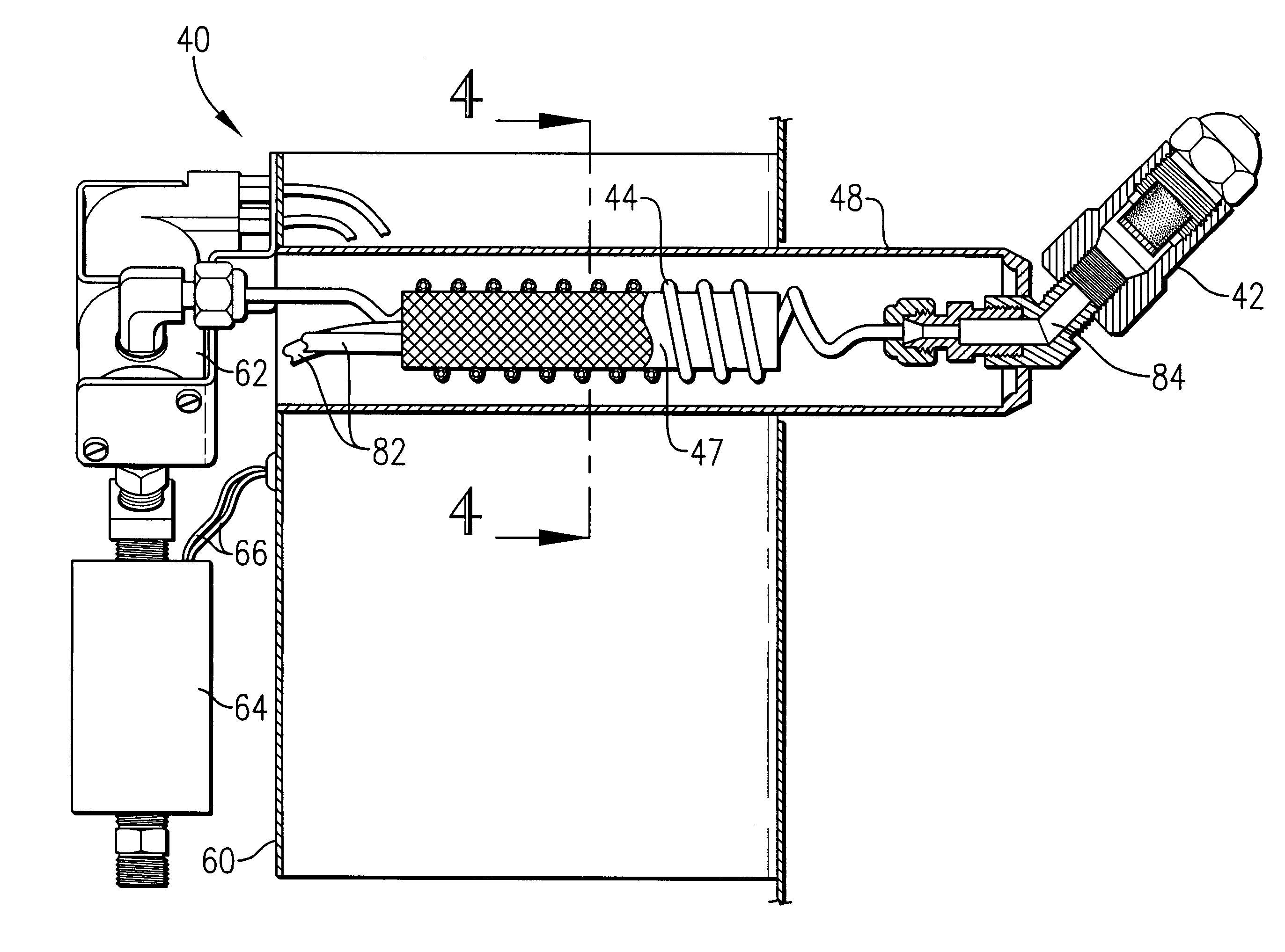
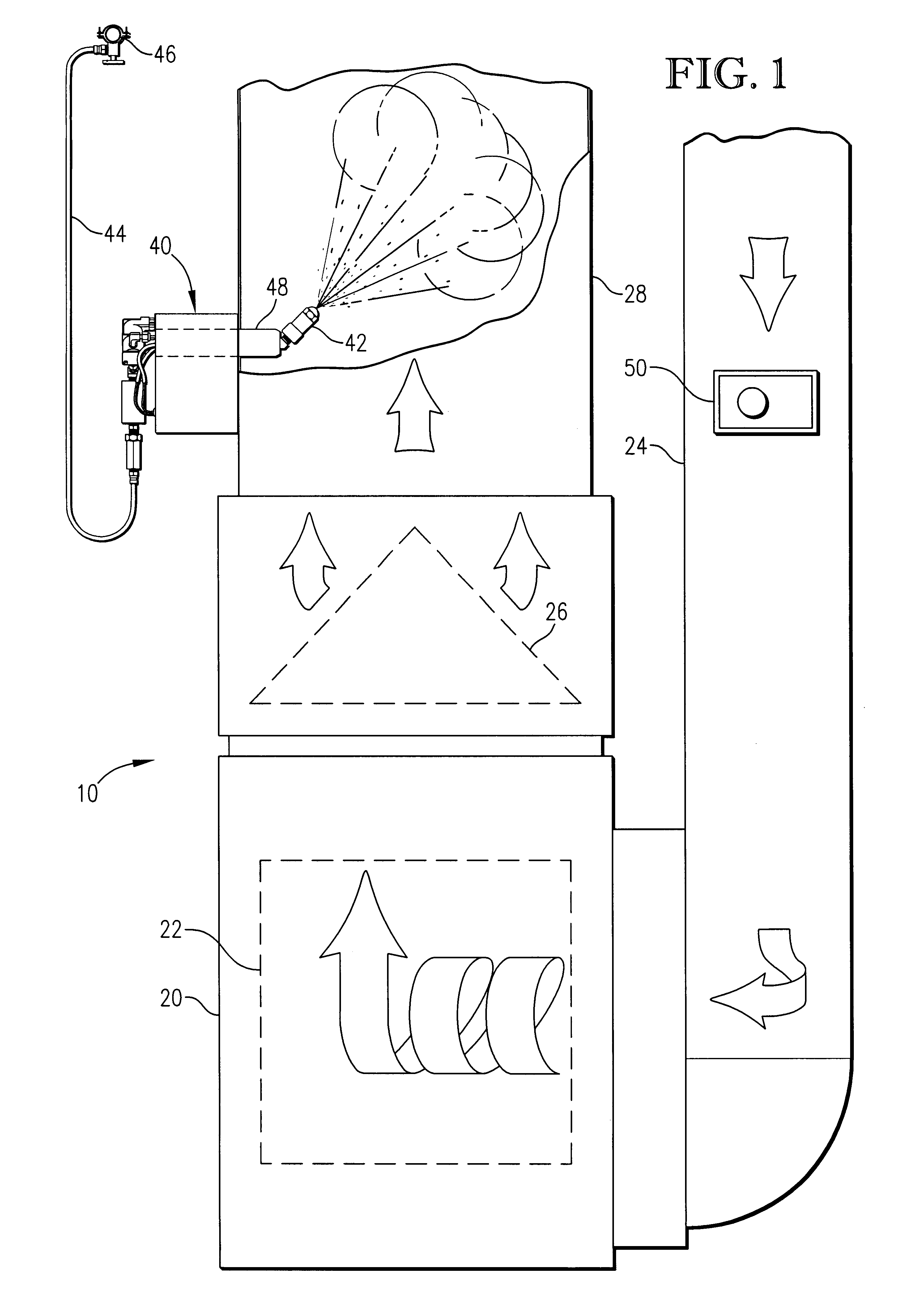
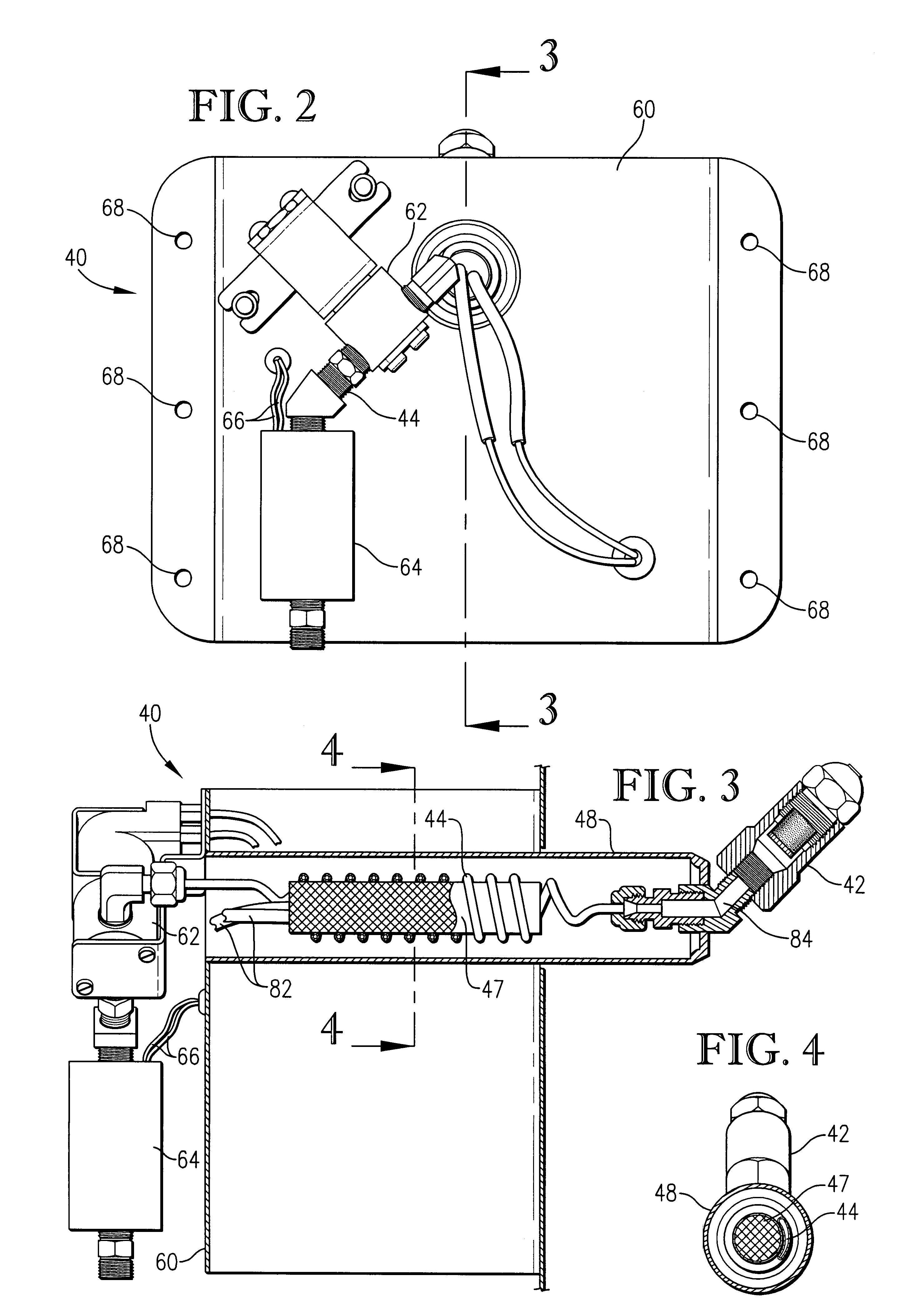
Referring to the drawings in greater detail, FIG. 1 depicts a heating and humidifying system 10 of the present invention including a heater 20 having a furnace 22, a return duct 24, air conditioning coils 26, and a plenum 28. Mounted to heater 2030 is humidifier 40. Humidifier 40 includes a nozzle 42 mounted so as to protrude into the plenum 28 of the heater 20. The nozzle 42 is in communication with a water line 44 that is connected to a continuous pressurized water source 46. The continuous pressurized water source 46 may come from, for example, a household water connection whose source may be a municipal water utility, a well, or any other convenient source of pressurized water. The water source used may be either cold or hot water, but is preferably a cold water source so as to avoid placing further demands on the hot water system contained within the building being serviced by the system of the present invention. The water line passes in close proximity to a heating element 47 ...


PUM

PropertyMeasurementUnit
Temperatureaaaaaaaaaa
Flow rateaaaaaaaaaa
Lengthaaaaaaaaaa

Abstract

A steam humidifier for use with a forced air heating system includes a steam nozzle mounted in the plenum of the heating system and connected to a water feed line connected to a continuous pressurized water source. The water feed line is made of a thermal conducting material and is coiled about a heating element wherein the heating element and conductive coil are substantially surrounded by an insulation barrier. The water feed line is controlled by a solenoid operated valve that will be activated only when the heater is on and a humidistat detects that humidity is required by the area being serviced by the forced hot air system.

Description

1. Field of the InventionThis invention relates to humidifiers that are used in forced hot air heating systems. Specifically, this invention relates to an improved apparatus and method for introducing steam into a heated air stream in such a system.2. Description of the Prior ArtIt is well known that forced air heating systems tend to create an atmosphere in a building space characterized by low relative humidity which leads to occupant discomfort and possible health problems, damage to wooden articles including furniture contained within the building, and the discomfort caused by static electricity discharges. To obviate these problems, it is common practice to employ devices for adding moisture to the air being forced through the building space. In this regard, a wide variety of devices are commonly employed. For example, evaporative type systems are installed in the furnace plenum or heating ducts so that heated air is forced to flow through and about sponge-like members that are...

Claims


Application Information

Patent Timeline
IPC IPC(8): B01F3/00B01F3/02B01F15/00B01F23/10
CPCB01F3/022B01F15/0024B01F15/00123F24F2006/146F24F11/0015F24F11/30F24F2110/20B01F23/12B01F35/20B01F35/2135F24F11/46B01F35/21
Inventor LIGHT, BARRY D.ROBERTS, TIMOTHY W.
Owner ALLIED SYST RES
Why Eureka
Try Eureka