One piece cutter body

a cutter body and cutter head technology, applied in the direction of gear teeth, manufacturing tools, manufacturing apparatus for gear teeth, etc., can solve the problems of internal weaknesses, thermal distortion in the slots which receive individual cutting blades, and weaknesses in this region

Inactive Publication Date: 2002-06-04
DANA CORP
View PDF9 Cites 11 Cited by
  • Summary
  • Abstract
  • Description
  • Claims
  • Application Information

AI Technical Summary

Problems solved by technology

This method of assembling the concentric members of the cutter head is known to cause thermal distortion in the slots which receive the individual cutting blades.
This method of assembly also results in internal weaknesses, particularly at the interface between the first disk-like member and the second backing ring member.
When a disk-like body member and a ring member are welded together, for example, thermal stresses are set up in the region of the interface, resulting in weaknesses in this region.
These weaknesses in the cutter body or cutter head allow the cutter head to be easily damaged and may lead to eventual failure.
Upon damage or failure of the cutter head, attempts to repair the cutter head prove to be difficult and expensive, to the extent that such procedures are prohibitive and generally not employed.
The damage or failure of the cutter head may also simply not be repairable.
The two-piece configuration may further result in errors in positioning of the components which can translate into errors in cutting operations using the cutting head.

Method used


Image

  • One piece cutter body
  • One piece cutter body
  • One piece cutter body

Examples


Embodiment Construction

This invention will now be described in detail with particular reference to the best mode and preferred embodiment thereof

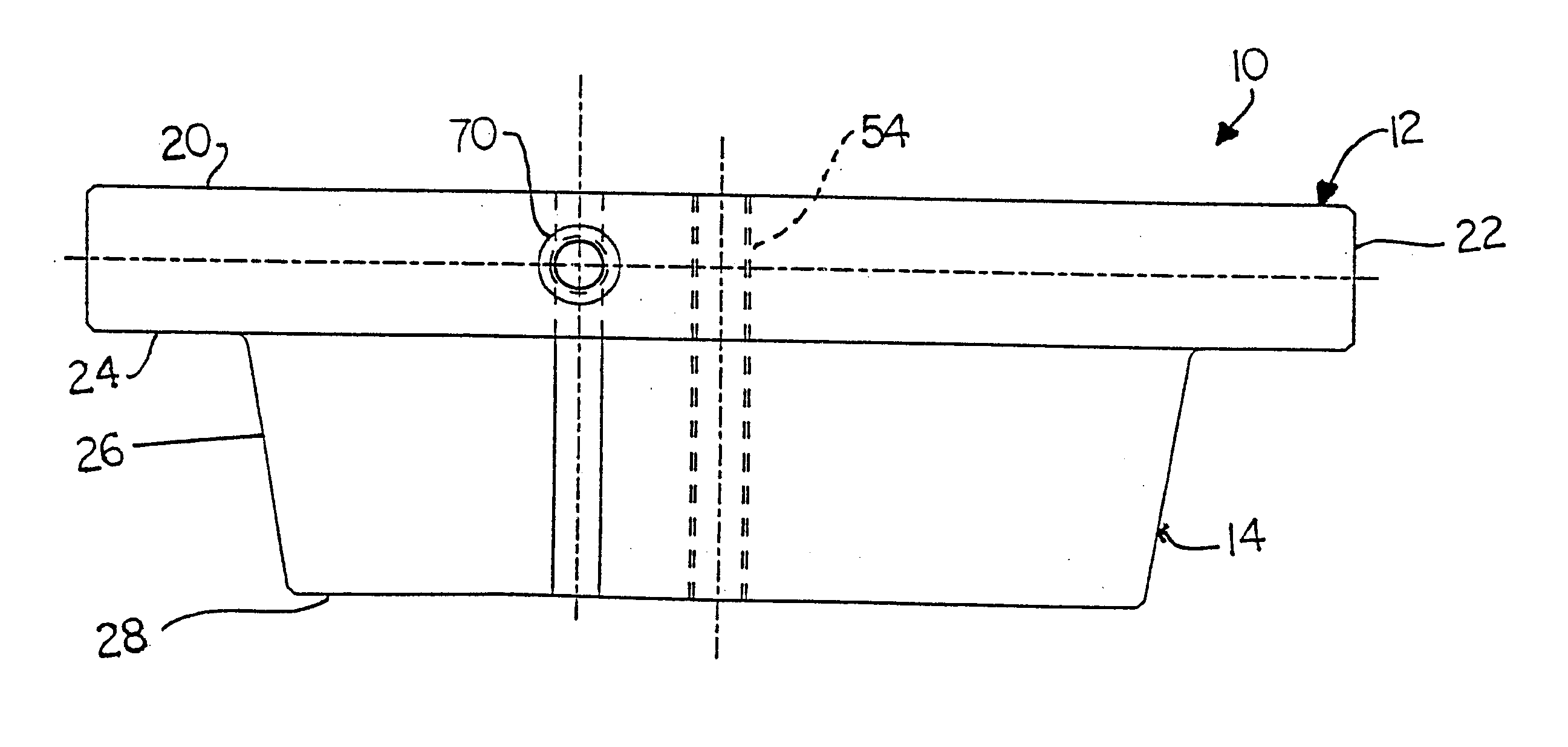
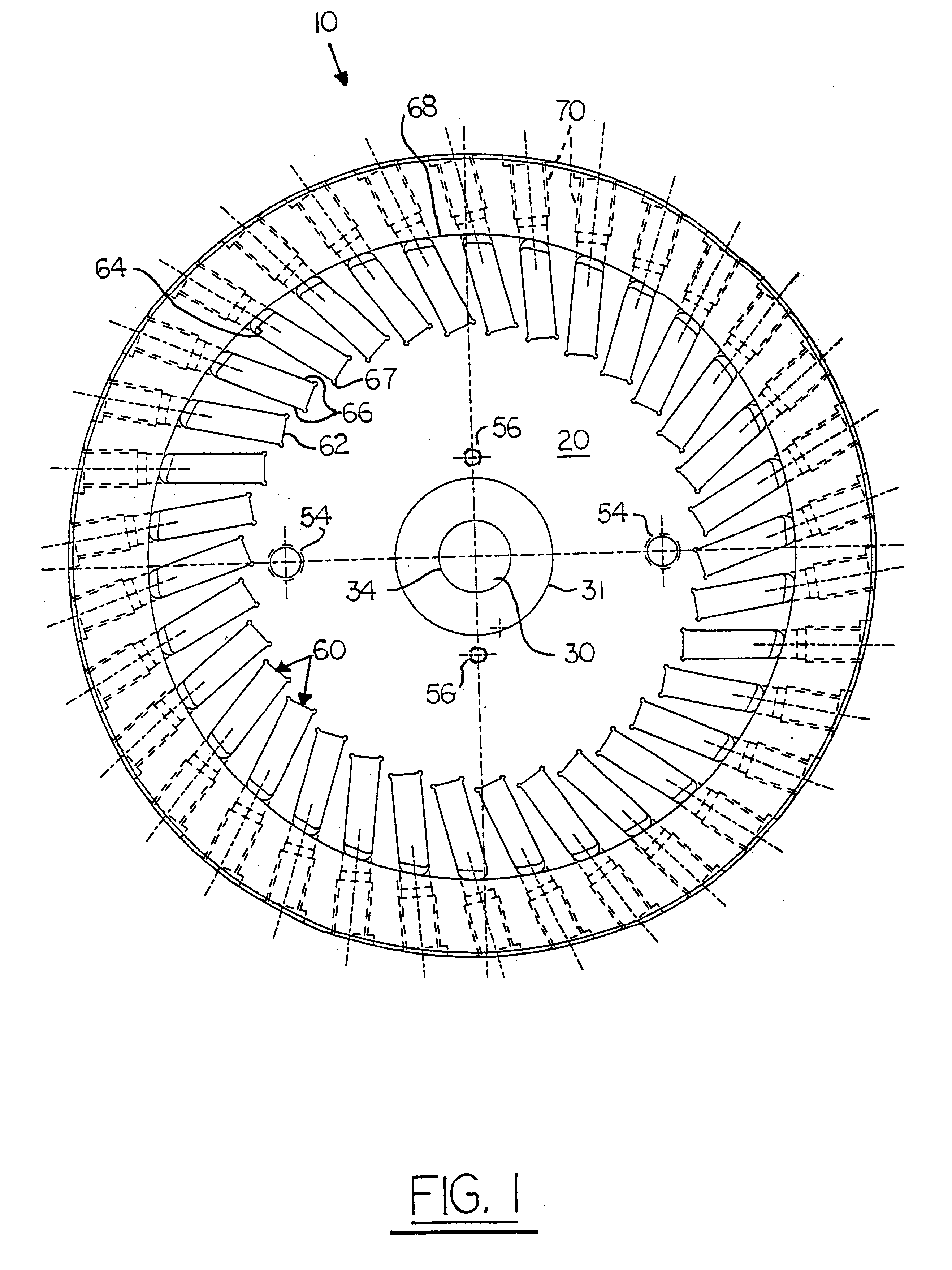
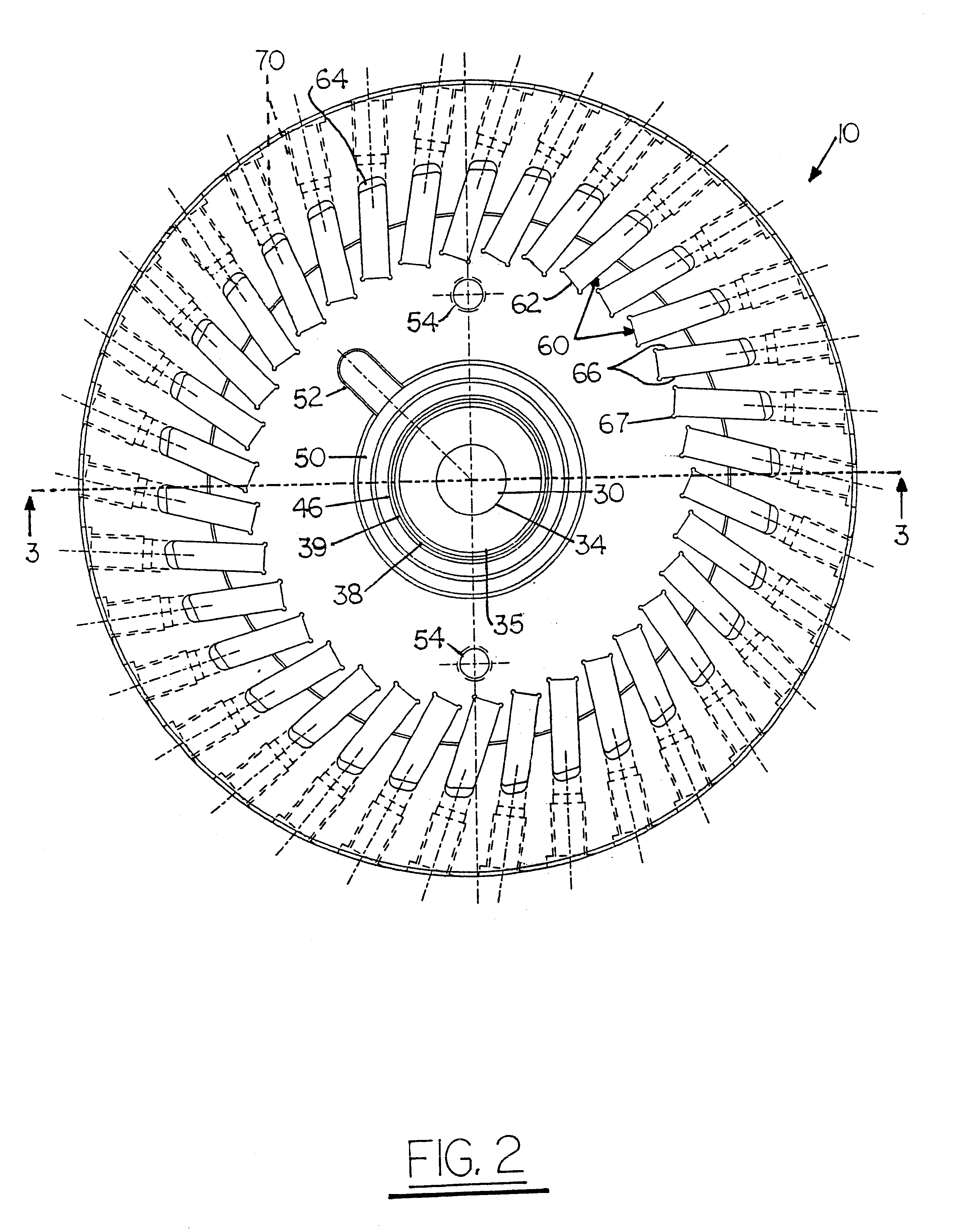
Referring now to FIGS. 1-4 of the drawings, 10 is one-piece cutter body or cutter head according to this invention. The preferred cutter body 10 is a surface of revolution comprising a cylindrical portion 12 and a frustoconical portion 14 which have a common central axis A as shown in FIG. 4. Frustoconical portion 14 projects axially in one direction from the cylindrical portion 12.

Cutter body 10 is formed from a single piece of metal as will be hereinafter described. Hence the cylindrical portion 12 and the frustoconical portion 14 are integrally formed with no interface or weldment between the two sections.

The cylindrical portion 12 of cutter body 10 has a planar first end face 20, which is circular in shape and perpendicular to central axis A. A cylindrical sidewall 22 extends around the circumference of end face 20 and intersects the end face at right angles....


PUM

PropertyMeasurementUnit
depthaaaaaaaaaa
timeaaaaaaaaaa
outer diameteraaaaaaaaaa

Abstract

One-piece cutter body for gear cutting operations. The one-piece cutter body has a plurality of circumferentially spaced slots for receipt of gear cutting blade. The slots are formed by a heatless electroerosive process, preferably electron-discharge machining (EDM) process utilizes computer numerical control (CNC) methods. A cutter body having outstanding strength and durability with highly precise slot configurations is obtained.

Description

1. Field of the InventionThis invention relates to a cutter head or cutter body for a cutting assembly which is used in gear cutting operations.2. Background ArtSpiral bevel, zerol and hypoid gears are well known and widely used throughout the automotive industry in a variety of drivetrain applications. Conventional methods for making each of these gears include face milling and face hobbing, with the two methods producing different gear tooth geometry which must be taken into consideration during the gear design. Gears produced by face milling typically have a tapered tooth depth, with the heel end of the tooth being deeper than the toe end of the tooth but they may also have uniform depth teeth. In contrast, gears produced by face hobbing always exhibit a uniform tooth depth. Face milling is an intermittent indexing process which cuts one tooth at a time and then indexes to the next slot so as to cut the adjacent tooth. This process is repeated until all of the teeth have been cut...

Claims


Application Information

Patent Timeline
Patent Type & Authority Patents(United States)
IPC IPC(8): B23F21/22B23F21/00
CPCB23F21/226Y10T409/103816Y10T409/106042Y10T407/171
Inventor HERENDEEN, MAX E.KELLER, KENNETH J AREUVERS, ANDREW A.
Owner DANA CORP
Why Eureka
Try Eureka