
Video monitor adjustment system

a video monitor and adjustment system technology, applied in the field of microprocessor controlled video monitors, can solve the problems of complicated image quality adjustment operation, operator's inability to perform adjustment operation, and operator's inability to observe a displayed image,

Inactive Publication Date: 2002-06-04
EIZO NANAO
View PDF20 Cites 31 Cited by
  • Summary
  • Abstract
  • Description
  • Claims
  • Application Information

AI Technical Summary

Benefits of technology

A combination of the four-way input switches and the input confirmation switch enables convenient operation; the four-way input switches may be used for selecting adjustment items and for incrementing and decrementing parameter settings, while the input confirmation switch may be used for setting the selected adjustment item and the adjusted parameter. When the four-way input switches are used in this way, upward and rightward directions may be used for incrementing operation, and downward and leftward directions for decrementing operation. With this arrangement, a selected parameter can be varied on a real-time basis through the microprocessor in accordance with the duration of time each switch is held pressed.
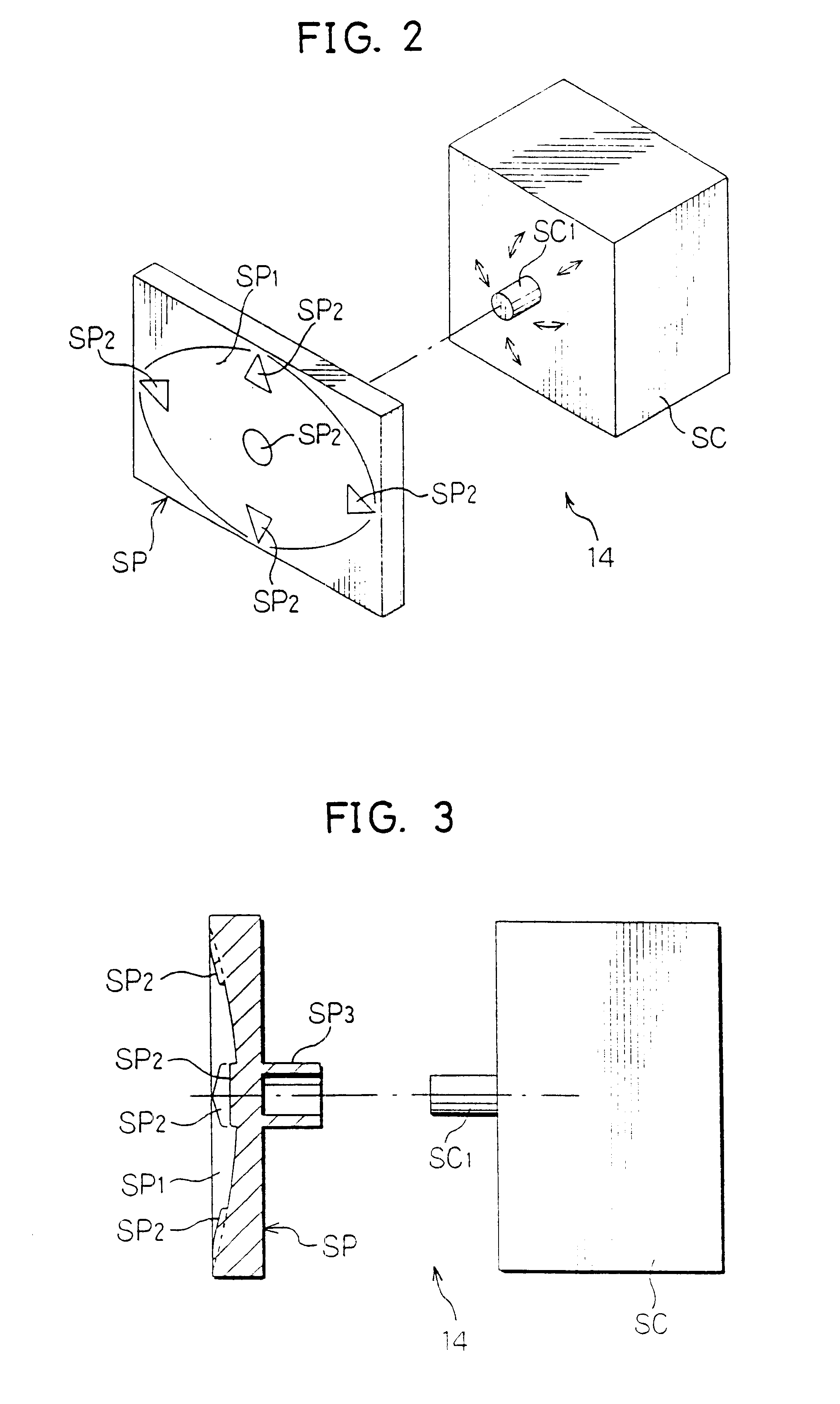
If the input device is an operating switch unit into which the four-way input switches and the input confirmation switch are integrally incorporated, the operator can selectively operate the four-way input switches and the input confirmation switch only by slightly changing his, or her, switch pressing position. This enables the operator to complete each adjustment sequence while observing the screen of the video monitor,-without having to look at the operating switch unit. It is preferable that the operating switch unit operated in this manner have a physical size that is suitable for a fingertip adjustment, and projecting markings corresponding to the four-way input switches and the input confirmation switch be formed on its surface.
In this case, the microprocessor can make it even easier to select a desired adjustment item from those shown on a submenu window by presenting icons, which prompt the operator to increment or decrement the settings of the two parameters, at the same position within the submenu window based on a time-division scheme. Since the selected adjustment item, or icons corresponding to that adjustment item, are alternately displayed with the lapse of time, the operator can intuitively recognize the content of adjustment and carry out the operation.
Alternatively, the microprocessor may simultaneously display functions of the individual directional input switches by presenting all icons, corresponding to incrementing and decrementing operations of the two parameters, on an adjustment screen at the same time, rather than presenting them based on a time-division scheme. More particularly, icons corresponding to the incrementing and decrementing operations of the two parameters may be displayed at top, bottom, left and right positions on the screen so that they correspond to the incrementing and decrementing functions of the four-way input switches, and an icon corresponding to a directional input switch pressed by the operator may be emphasized in its appearance, for instance. This arrangement would enable the operator to distinctly recognize the content of each operation. Preferably, the icon should be emphasized by showing it in an inverted video, or temporarily surrounding it by a box or underscoring it. This is because a video emphasis technique of this kind is effective for saving the capacity of the nonvolatile memory, when compared to a method of displaying a completely different icon.
According to the invention, it is possible to present the individual adjustment items on the screen of the video monitor to allow the operator to select a desired adjustment item, as well as messages necessary for carrying out parameter setting and other adjustment operations on the same screen. This permits the operator to easily adjust the image quality within a short period of time. Moreover, the integrated four-way input switches make it possible to perform the adjustment operations without looking at the fingertips and to increment or decrement the settings of two parameters at the same time. This provides such advantageous effects that operator input efficiency is significantly improved, and this enables the operator to execute adjustment work in a reliable and efficient manner.

Problems solved by technology

One drawback of this arrangement is that the operator can not perform adjustment operation unless he, or she, is fully aware of the content of each icon and skilled in every adjustment procedure.
Another drawback of the conventional arrangement is that the operator can not carry out adjustments while observing a displayed image.
The image quality adjustment operation has therefore been complicated and taking a lot of time.

Method used


Image

  • Video monitor adjustment system
  • Video monitor adjustment system
  • Video monitor adjustment system

Examples


Embodiment Construction

A specific embodiment of the invention is now described with reference to the accompanying drawings.

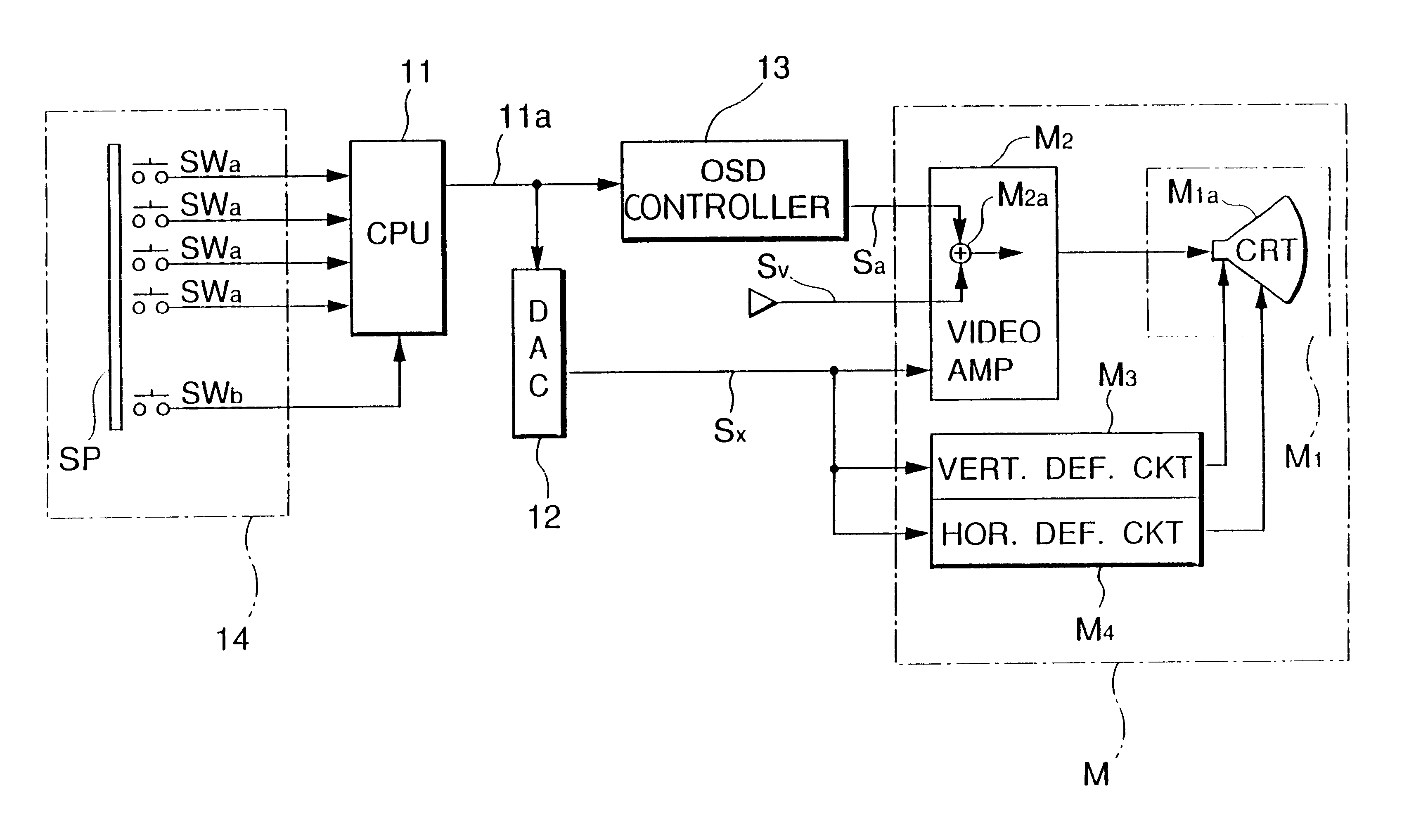
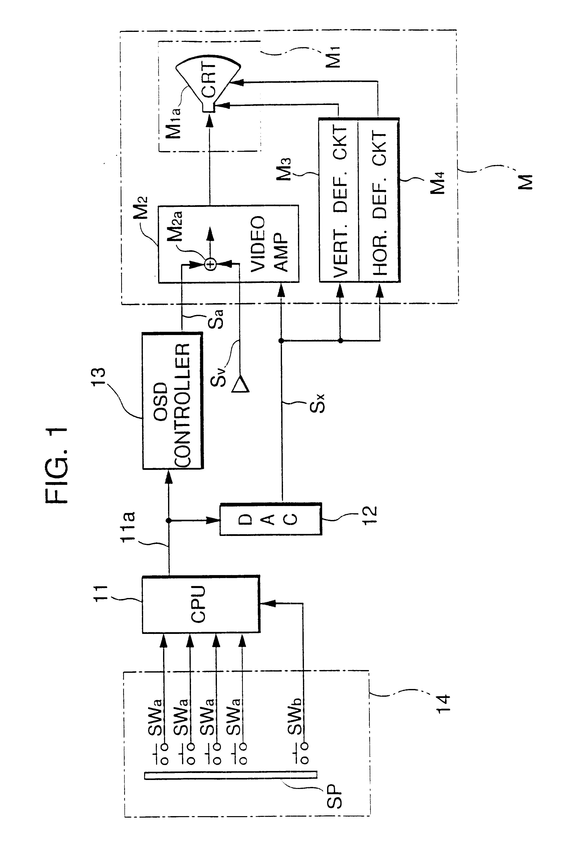
Referring to FIG. 1, a video monitor adjustment system mainly comprises an on-screen display controller circuit 13 which displays a plurality of adjustment items in the form of icons together with a visual message explaining the content of each icon on a display screen of a video monitor, an operating switch unit 14 used as an input device for selecting a desired icon displayed on the screen and setting a parameter corresponding to the selected icon, the operating switch unit 14 including an operating element into which four-way input switches for specifying upward, downward, leftward and rightward directions and an input confirmation switch are integrally incorporated, and a microprocessor 11 serving as a image quality controller which identifies a selected adjustment item based on an icon selection command entered through the operating switch unit 14 and adjusts image quality adjust...


PUM


Abstract

Directed to an adjustment system for adjusting image quality of a video monitor by using a microprocessor, the present invention simplifies complicated operation in image quality adjustment and thereby eliminates the need for high-level operating skills. The adjustment system comprises an on-screen display controller circuit which can display a plurality of adjustment items in the form of icons together with a visual message, explaining the content of each icon, on a screen of the video monitor and an input device used for selecting a desired icon and setting a corresponding parameter, the input device being constructed of four-way input switches which are integrally combined into a single button to perform adjustment functions. This construction enables an operator to perform adjustment operations in an integrated manner which have thus far been made individually, providing savings in the period of time required for adjustment work and simplification thereof.

Description

The present invention pertains generally to a video monitor connected to various computer systems and, more particularly, relates to an adjustment system for the video monitor which can perform image quality adjustment operation by using a microprocessor to ensure an optimum image quality when connected to a computer system.BACKGROUND TECHNOLOGYA microprocessor-controlled video monitor which can automatically adjust image quality adjustment parameters in accordance with the operation of different computer systems is conventionally known in the art (Japanese Unexamined Patent Publication No. 3-35287).To maintain an optimum image quality, the video monitor of this kind is so constructed that operating parameters of its individual circuits, such as a video amplifier circuit, a vertical deflection circuit and a horizontal deflection circuit, are set to match a computer system to which the video monitor is connected. A control processor performs image quality adjustments by setting speci...

Claims


Application Information

Patent Timeline
Patent Type & Authority Patents(United States)
IPC IPC(8): G09G1/16H04N17/04H04N5/445G09G1/00G09G5/00
CPCG09G1/165H04N17/04G09G2320/0606G09G2320/0626H04N21/485G09G2320/08G09G2320/066
Inventor HIRAKA, TADAHIKOTORII, HAJIME
Owner EIZO NANAO
Learn More