Balloon-assisted intraluminal stent graft

a balloon-assisted, intraluminal technology, applied in the field of intraluminal devices, can solve the problems of inability to accommodate variations in patient physiology, undesirable clinical use, and occasional mortality, and achieve the effect of recurrence, and reducing the risk of recurren

Inactive Publication Date: 2002-06-11
LEMAITRE ACQUISITION +1
View PDF57 Cites 129 Cited by
  • Summary
  • Abstract
  • Description
  • Claims
  • Application Information

AI Technical Summary

Problems solved by technology

These types of procedures can cause major trauma to the patient with corresponding lengthy recovery periods, and may result in occasional mortality.
All of these devices have a number of drawbacks that make them undesirable for clinical use.
First, devices made of non-expandable materials and having predetermined deployed diameters cannot accommodate variations in patient physiology, and changes in diameter between the distal and proximal implantation site.
Second, devices with plastically deformable stents cannot withstand external compression without deformation of the stents, limiting the use of the devices in patient's extremities.
Third, fully self-expanding devices must be deployed through a sheath, which typically compels the user to deploy the devices linearly, i.e. from the proximal to the distal end.
A problem with these types of tubes is that because of the limitations of the machinery and processes used to produce them, their wall thickness becomes large once the tube diameters exceed 8 mm and hence cannot be used for many prostheses requiring grafts of up to 25 mm in diameter.
Moreover, standard ePTFE tubes cannot be expanded radially because they have a tendency to lose strength and split when they are dilated.
The only limitation on this process is that the mandrel cannot have a smaller diameter than the inner diameter of the initial ePTFE (i.e., the tube made by extrusion).

Method used


Image

  • Balloon-assisted intraluminal stent graft
  • Balloon-assisted intraluminal stent graft
  • Balloon-assisted intraluminal stent graft

Examples


Embodiment Construction

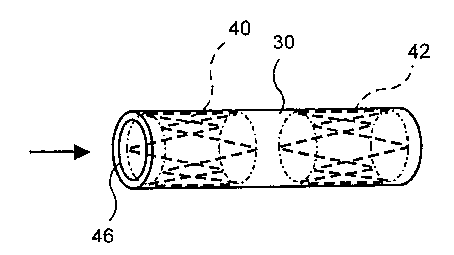
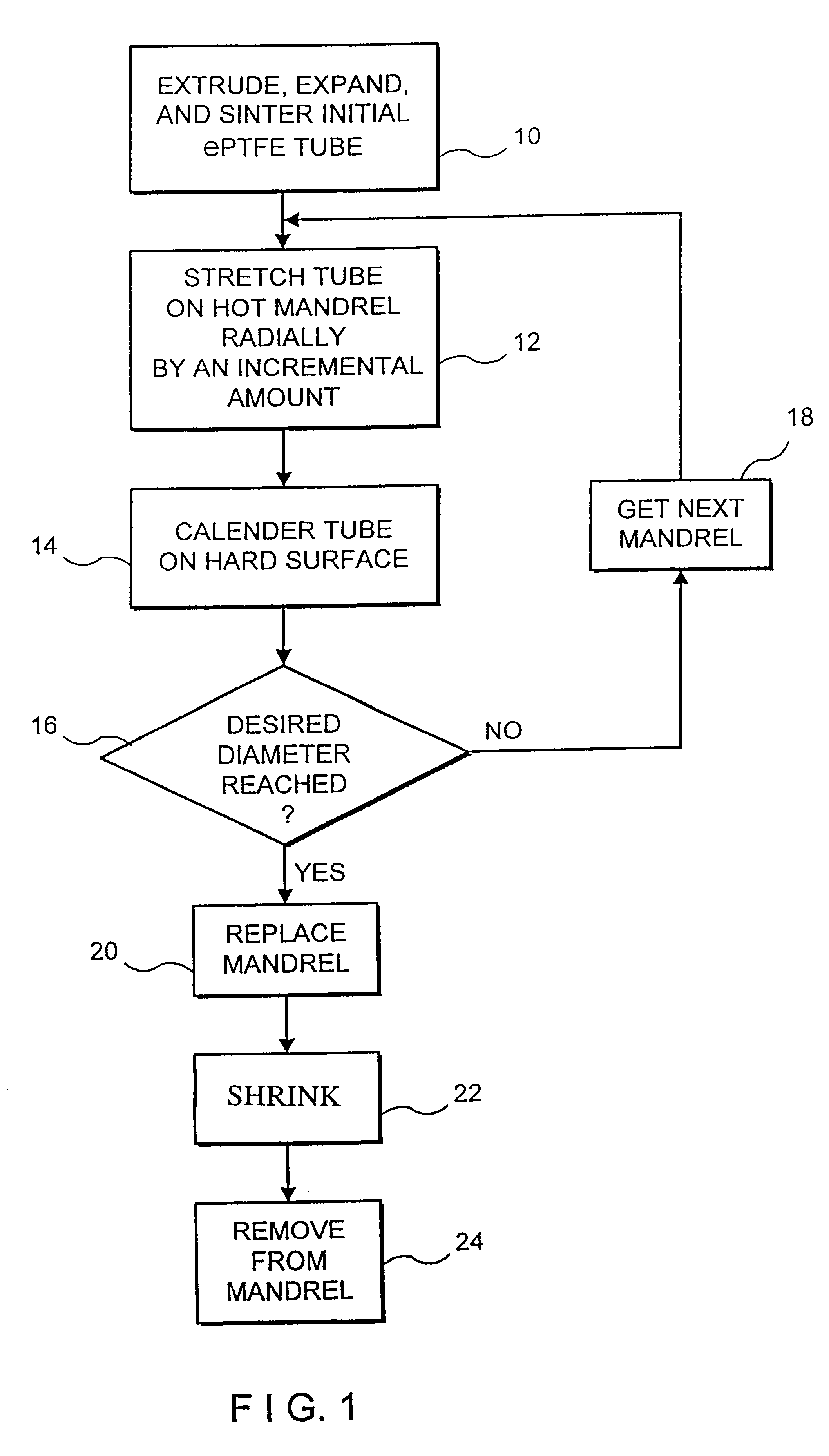
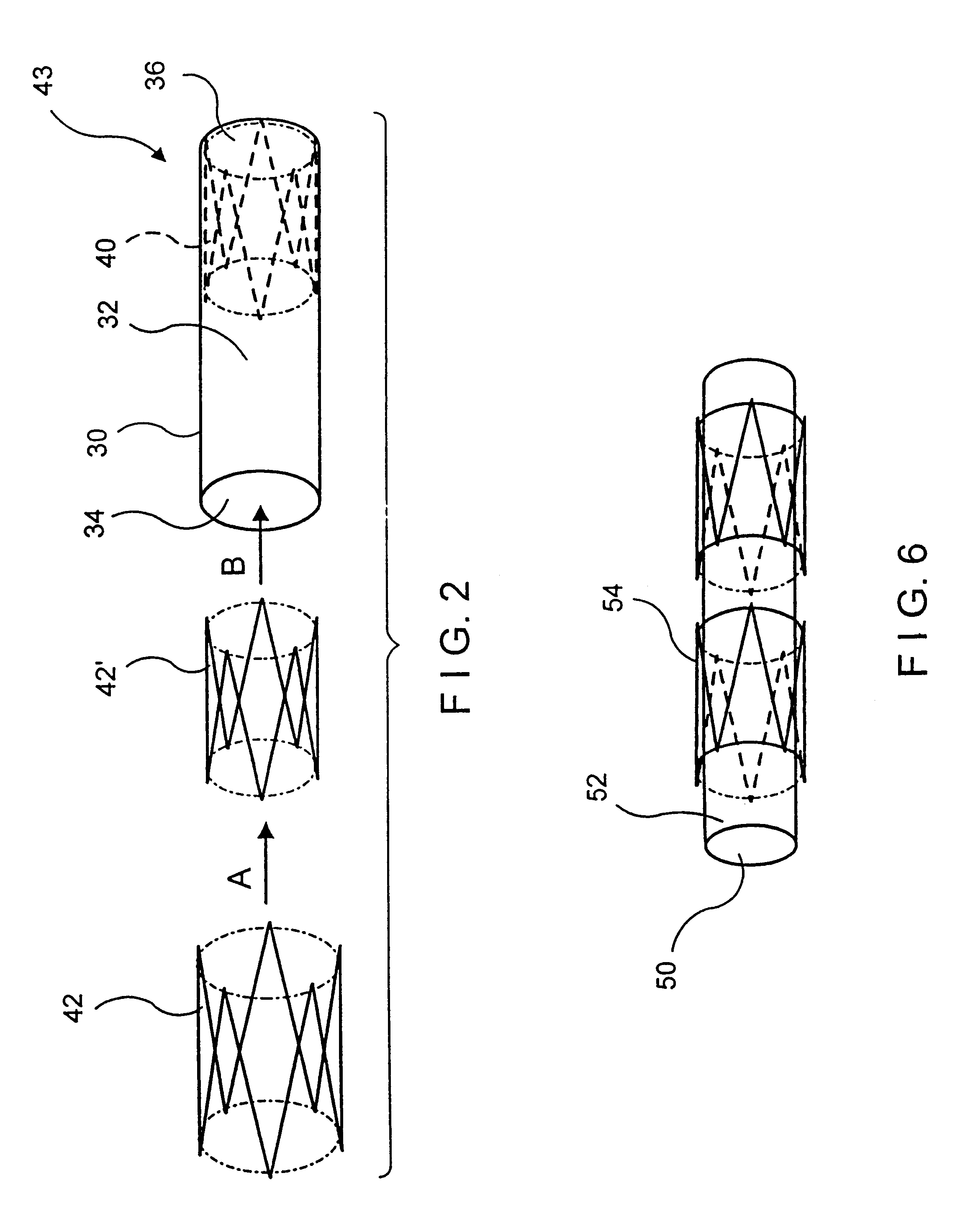
In accordance with this invention, an intraluminal device comprising a conformable ePTFE tube is made in three stages illustrated in FIG. 1. The first stage consists of making an initial ePTFE tube. This stage is well known in the prior art and is performed as follows:

a. A PTFE resin is compounded with a lubricant (preferably a petroleum distillate, such as naphtha);

b. The compound is compacted under pressure;

c. The compacted mass is extruded into a tube using a standard ram extrusion process to its predetermined diameter;

d. The tube is dried to remove the lubricant;

e. The dried tube is stretched longitudinally by up to 1000%;

f. The longitudinally stretched tube is sintered or cured at high temperature while its ends are fixed to insure that the tube does not shrink to its original length.

This stage is represented in FIG. 1 as step 10. As explained previously, because of various limitations associated with the extrusion process (including, for example the maximum extrusion force tha...


PUM

PropertyMeasurementUnit
diameteraaaaaaaaaa
diameteraaaaaaaaaa
diameteraaaaaaaaaa

Abstract

An intraluminal device such as a stent graft is formed of a conformable ePTFE tube and preferably a compressed self-expanding stent affixed to the tube. The conformable tube is made by a special process which insures that the tube is radially deformable up to a predetermined diameter without exceeding the plastic deformation limit of the tube. The stent has a relaxed diameter larger than the diameter of the expanded tube after insertion so that the tube is biased to a cylindrical shape. The process for making the tube involves progressively dilating a small diameter extruded tube until a desired diameter is achieved. The tube is then contracted on a small diameter mandrel by heating.

Description

A. Field of InventionThis invention relates to the field of intraluminal devices and particularly to intraluminal grafts useful as an inner lining for blood vessels or other body conduits. More particularly, the present invention provides tubular structures which can be expanded in a transversal direction to conform to the diameter of a particular vessel in a patient's anatomy.B. Description of the Prior ArtConventional vascular grafts have been used routinely for the repair of the human vasculature. These devices are typically flexible tubes of woven or knitted polyethylene terephthalate (PET or Dacron .RTM.), porous polytetrafluoroethylene (PTFE) or porous polyurethane (PU). Grafts of biological origin have also been used, typically comprising preserved human umbilical or bovine arteries. These conventional vascular grafts usually require invasive surgical procedures for insertion to expose at least the two ends of the segment of vessel to be repaired. Frequently, it is necessary ...

Claims


Application Information

Patent Timeline
Patent Type & Authority Patents(United States)
IPC IPC(8): A61F2/06A61F2/00A61F2/07A61L27/00
CPCA61F2/07A61F2002/072A61F2220/005A61F2250/0063A61F2/89A61F2002/075
Inventor COLONE, WILLIAM M.FARL, KEVIN G.TEETER, BARBARA L.CREER, WILLIAM L.SINNOTT, JOSEPH B.
Owner LEMAITRE ACQUISITION
Why Eureka
Try Eureka