Blow-molded container having reinforcement ribs and method and apparatus for making same

a technology of reinforcement ribs and containers, which is applied in transportation and packaging, water/sewage treatment by ion exchange, and separation processes, etc., can solve the problems of reducing limiting the ability of manufacturers to reduce the amount of plastic consumed, and significant expense in the manufacture of blow-molded containers. achieve the effect of stiffening the container, enhancing structural performance, and enhancing top loading capability

Inactive Publication Date: 2002-06-18
DEUT BANK TRUST COMPANY AMERICAS
View PDF24 Cites 23 Cited by
  • Summary
  • Abstract
  • Description
  • Claims
  • Application Information

AI Technical Summary

Benefits of technology

When a container 10 is made from HDPE, or like plastic, the ribs 26 are not visually perceptible when viewing the exterior surface 18 of the filled container 10. In addition, most known container configurations which are produced by blow molding techniques can be blow molded with the ribs 26. Thus, container configurations which are already known and favored by consumers and which provide brand recognition, can be blow molded in the same molds to produce identical appearing containers which differ only in that ribs are blown integral on the inner walls of the container to structurally reinforce and stiffen the container. If a given container is made from an equal amount of plastic, the ribbed version of the container made according to the present invention will provide enhanced structural performance, such as greater top loading capability. Alternatively, if the ribbed version of the container is to provide similar structural performance as the prior art non-ribbed version, the ribbed container can be manufactured from a reduced amount of plastic, and thus provide a cost savings. Such savings become significant when large quantities of a specific container design are manufactured. In addition, such

Problems solved by technology

A significant expense incurred in the manufacture of blow molded containers is the plastic required to make the containers.
The degree of container rigidity required for packing and shipping purposes limits the ability of manufacturers to reduce the amount of plastic co

Method used


Image

  • Blow-molded container having reinforcement ribs and method and apparatus for making same
  • Blow-molded container having reinforcement ribs and method and apparatus for making same
  • Blow-molded container having reinforcement ribs and method and apparatus for making same

Examples


Embodiment Construction

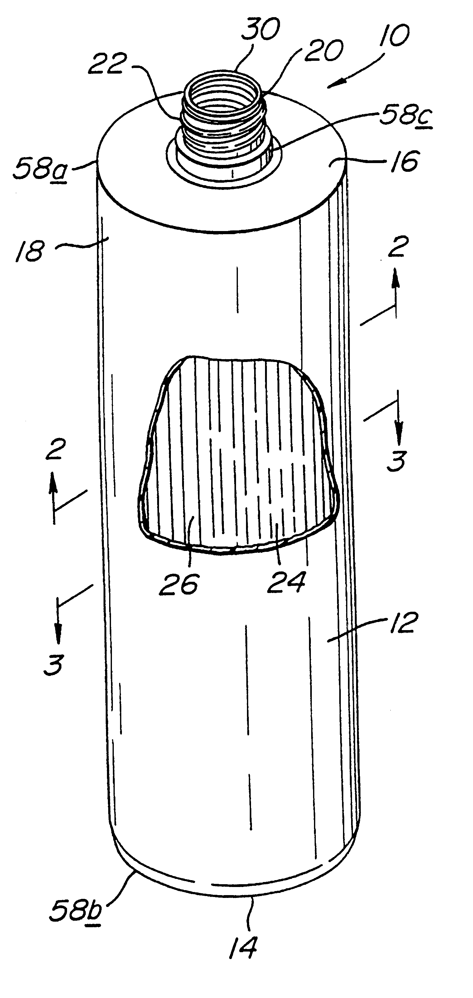
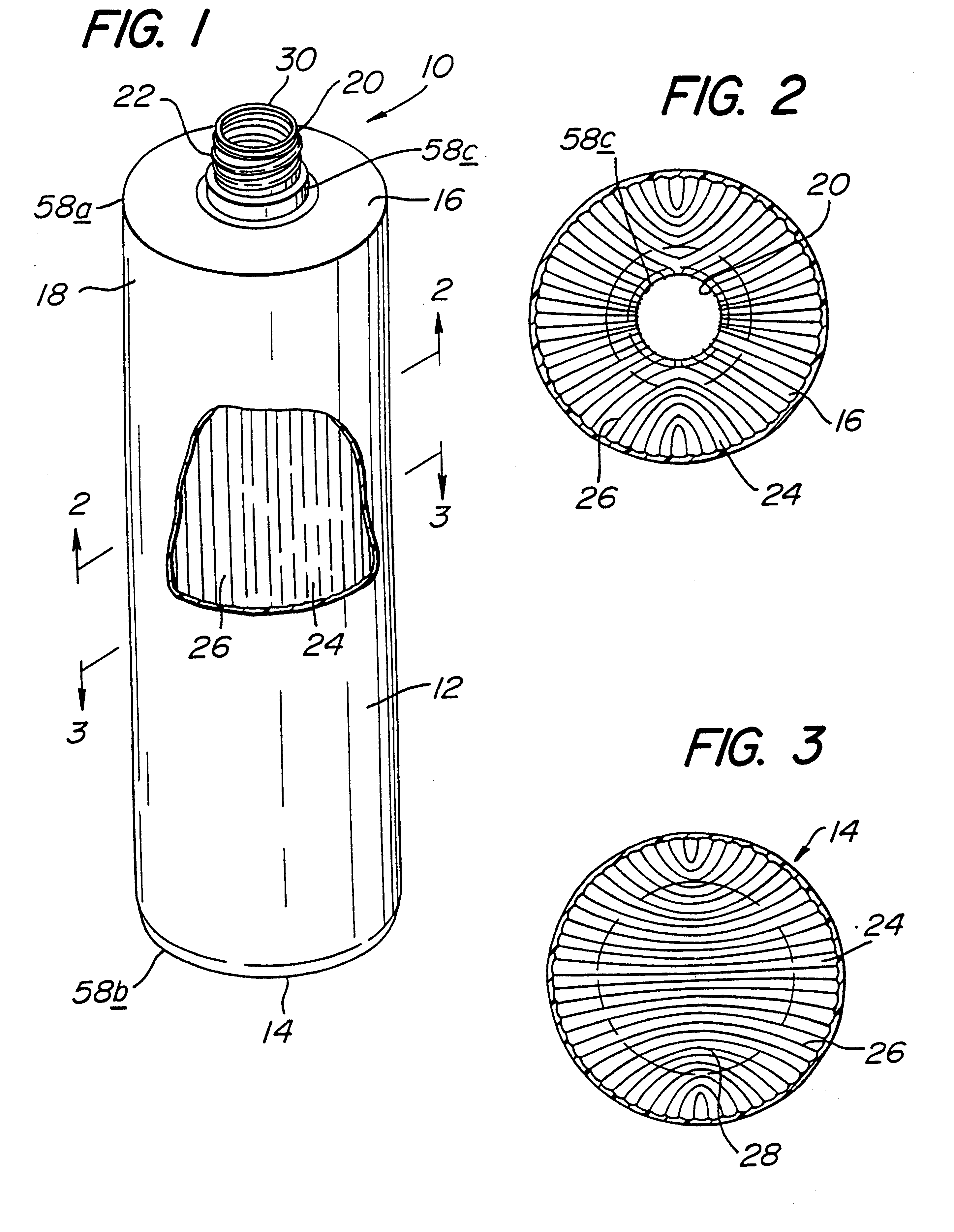
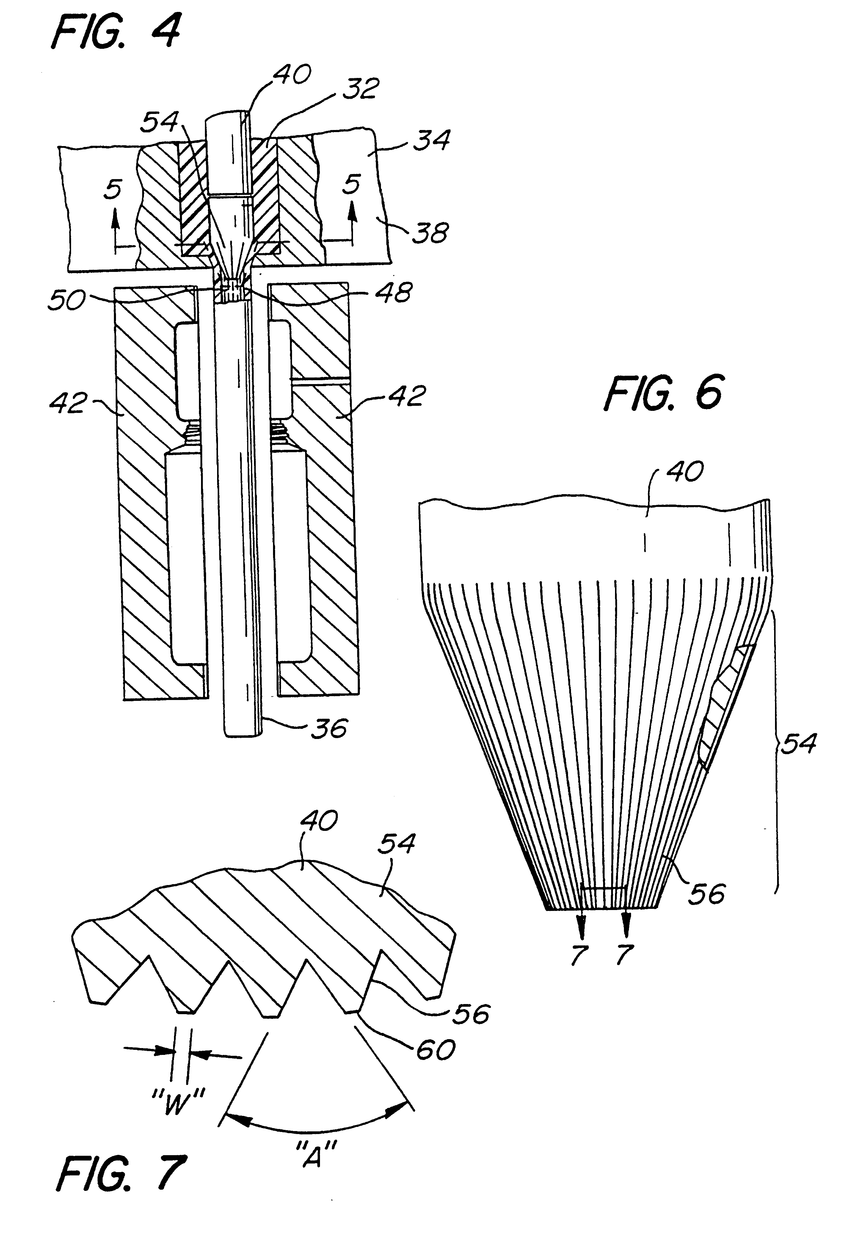
The container 10, discussed above, is produced by a novel method which is best illustrated in FIGS. 4 and 8. Molten plastic 32 is extruded through an extrusion head 34 to form a downwardly depending tubular parison 36. The extrusion head includes a die 38 and a mandrel 40.

As illustrated in FIG. 4, a pair of mold blocks 42 are positioned in an open condition adjacent the downwardly extending parison 36. When the parison is extruded a sufficient distance, the mold blocks 42 close around the parison 36 as illustrated in FIG. 8. A blow pin (not shown) is inserted into the mold 42 and the parison 36 to inflate the parison 36 into a container 44. After the container 44 is removed from the mold 42, the plastic moil 46 is removed and recycled.

A unique aspect of the method of the present invention is that the parison 36 is extruded with an inner peripherals wall 48 that has a number of continuous, longitudinally and inwardly extending ribs 50. Thus, the resulting container 44 is formed with ...


PUM

PropertyMeasurementUnit
Lengthaaaaaaaaaa
Widthaaaaaaaaaa
Lengthaaaaaaaaaa

Abstract

A blow-molded plastic container (10) providing enhanced top loading capability. The container (10) has an inner peripheral surface (24) on which a plurality of integral, solid, inwardly and longitudinally extending ribs (26) are formed. Preferably, the ribs (26) extend throughout the entire container inner surface (24) from the top edge of the finish (20) to a mold parting line (28) on the base (14). A method and apparatus for making the container (10) is also disclosed.

Description

The present invention relates to a sturdy blow-molded container made from a minimum of plastic, and more particularly, the present invention relates to a container having integrally formed inwardly extending ribs which enhance container stability and improve container top loading capabilities. The present invention also relates to a method and an apparatus for making a reinforced blow-molded container.Various household, automotive and other products, such as liquid, granular or gel products, including shampoo, detergents, motor oil, etc., are commonly packaged and sold to consumers in relatively small-sized, plastic, blow-molded containers, or bottles. For example, in excess of two billion one quart / one liter sized blow molded containers for packaging motor oil are sold annually in the United States alone. Because of the volume of the sales, improvements to the packaging of such products is of significant concern to the packaging industry and to consumers, especially those improveme...

Claims


Application Information

Patent Timeline
IPC IPC(8): B29C47/00B29C47/22B29C49/00B65D1/02B65D1/40B65D1/44B29C49/04B29C48/09B29C48/13B29C48/325
CPCB29C49/0078B65D1/0276B65D1/44B29C47/22B29C47/0023B29C47/003B29C47/0033B29C47/0054B29B2911/1434B29C49/04B29C48/09B29C48/12B29C48/13B29C48/0017B29C48/325B29C2949/074B29C2949/0741
Inventor CARGILE, DAVID W.
Owner DEUT BANK TRUST COMPANY AMERICAS
Why Eureka
Try Eureka