Calibration disk having discrete bands of composite roughness

a composite roughness and disk technology, applied in the field of disks, can solve problems such as loss of productivity, disk waviness and runout, and inducing fly height fluctuations

Inactive Publication Date: 2002-06-25
KOMAG CORP
View PDF3 Cites 104 Cited by
  • Summary
  • Abstract
  • Description
  • Claims
  • Application Information

AI Technical Summary

Problems solved by technology

This is because an impact between the magnetic head and a protrusion can cause undesirable effects, such as a hard drive crash, formation of wear debris, unusable recording area, a thermal spike in a magnetoresistive head and the like.
While magnetic disks are ideally flat and smooth, in practice there is typically an amount of disk waviness and runout.
Disk runout causes acceleration of the glide head which induces fly height fluctuations.
There are several drawbacks to the use of a fly height tester for calibration of a glide head.
Further problems encountered with using a fly height tester for calibration arise from the fact that the glide head is first installed on the fly height tester to determine fly height.
Installing the glide head on two separate systems is time consuming and thus results in a loss of productivity.
Differences in the installation on the two devices can cause differences in the flying characteristics of the glide head, including skew and mount flatness, thereby resulting in an inaccurate calibration of the glide head.
Variances in Z height can also adversely affect the repeatability of the flying characteristics of the glide head from the fly height tester to the glide tester.
Moreover, the surface of calibration disk 10 between the calibration bands would not be expected to be perfectly smooth.
The surface topology of the areas between the calibration bands can thus cause signal noise during calibration performed using calibration disk 10.
However, such noise can be ignored and therefore would not be expected to affect calibration.
The glide head flexes when contact is made with an asperity on the disk surface, causing the PZT sensor to experience mechanical stress.
As the fly height of the glide head is decreased below the avalanche height for the given calibration band, such contact appears as an increase in the noise observed in the signal generated by the PZT sensor.
At the extreme, roughness exhibits a "wavelength" (referred to herein as feature size) that is shorter (i.e., with a relatively high frequency) and even more difficult for the glide head to follow.
This is because roughness and micro-waviness may be either constructive or destructive, and so provides a range of composite roughness heights.
Unfortunately, scanning a disk surface using an AFM takes a substantial amount of time, and consequently, only a few data points are usually available when such a technique is employed, although an AFM may detect finer and / or higher features.
This is due to the acceleration from disk vibration and runout.
Even if composite roughness is decreased, waviness limits the glide avalanches.
Below the avalanche point, a typical glide head cannot sustain a no-contact condition because the average composite roughness height of peaks on the surface of the disk are higher than the fly height of the glide head.
Because each glide head must be independently tested on the fly height tester, the calibration procedure can be time consuming.

Method used


Image

  • Calibration disk having discrete bands of composite roughness
  • Calibration disk having discrete bands of composite roughness
  • Calibration disk having discrete bands of composite roughness

Examples


Embodiment Construction

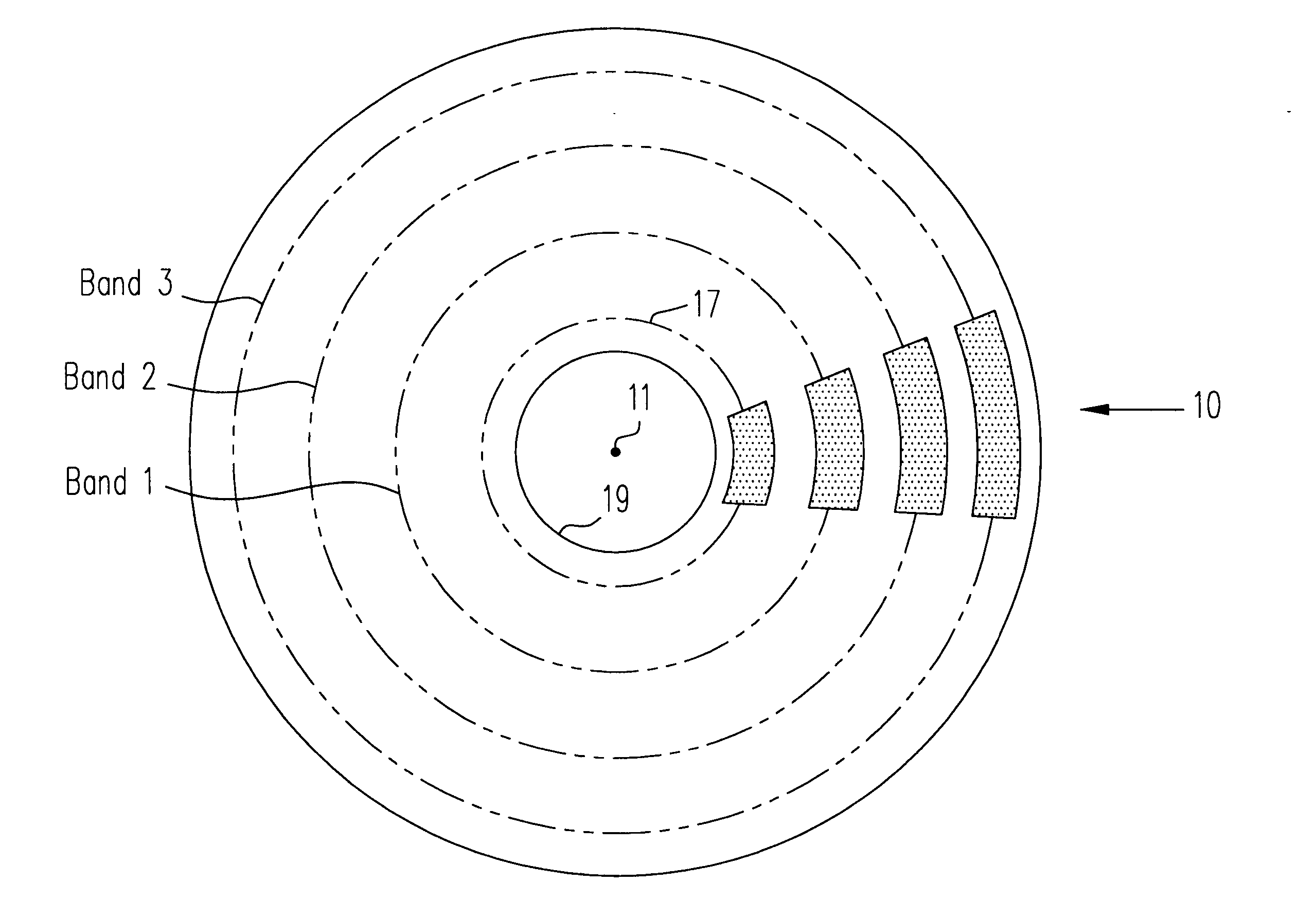
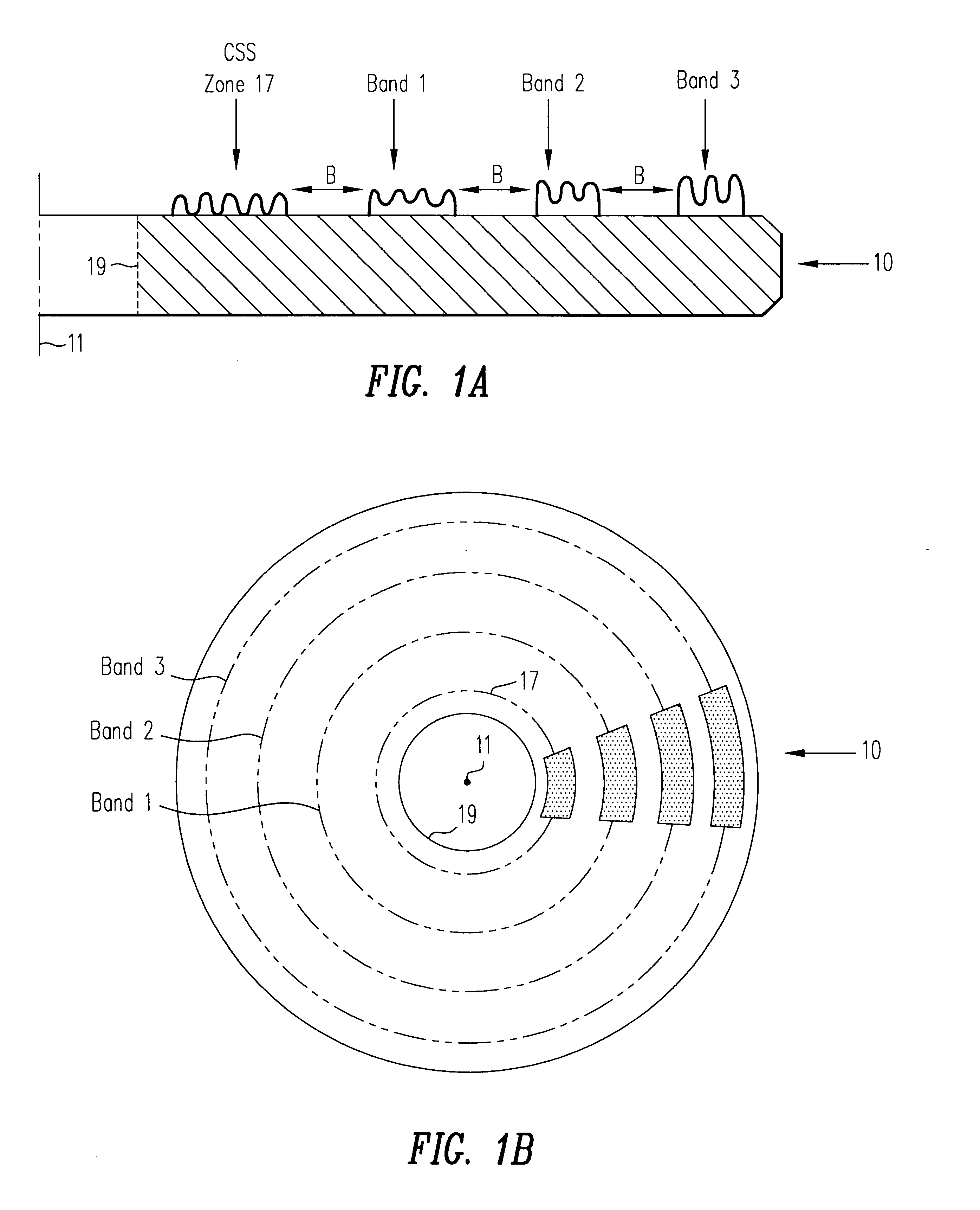
Calibration disk 10 can be used to calibrate a glide head while the glide head is on the glide tester by identifying the output signal generated by the lowest point on the glide head contacting calibration disk 10. An independent fly height measurement for the glide head need not be obtained on a separate fly height tester before mounting the glide head on the glide tester when using such a procedure. Calibrating the glide head while mounted on the glide tester simplifies calibration and advantageously eliminates variances caused by the difference between the glide tester and the fly height tester, such as Z height, skew, mount flatness, and disk parameters (e.g., clamping distortion, waviness, runout and the like). To calibrate a glide head with calibration disk 10 without using a fly height tester, one of the following procedures can be performed.

In one embodiment of the present invention, the glide head being calibrated is mounted on a glide tester, such as a model MG250 manufact...


PUM

PropertyMeasurementUnit
heightaaaaaaaaaa
heightaaaaaaaaaa
roughnessaaaaaaaaaa

Abstract

A calibration disk includes calibration areas that allow a glide head to be calibrated as to the glide's head's avalanche height, fly height and the like. The calibration areas may be, for example, configured in a circumferential band (or, alternatively, a series of circumferential bands extending substantially concentric to one another), one or more spiral bands or some other suitable configuration. Such bands can, for example, extend from adjacent an outer diameter of the calibration disk to adjacent an inner portion of the calibration disk. Each of the circumferential bands is a textured area on the calibration disk having a given degree of composite roughness, as measured by the given circumferential band's average composite roughness height, and as such is referred to herein as a calibration band. Preferably, the given circumferential band is textured in a uniform manner, sufficient to produce a constant and continuous output signal from a sensor mounted on a glide head when the glide head flies lower than a maximum composite roughness height. Also preferably, the average composite roughness height within an individual calibration band is substantially uniform, and the average composite roughness height of each calibration band is slightly different from that of the other calibration bands.

Description

1. Field of the InventionThe present invention relates to a calibration disk that can be used for calibrating a glide head, used in the process of manufacturing hard memory disks.2. Description of the Related ArtThe key components of a hard disk drive are a magnetic disk and a magnetic head, which is typically separated from the magnetic disk by a small gap. The gap is created by the magnetic head remaining relatively stationary while the magnetic disk rotates on a spindle. The rotation of the magnetic disk generates a thin film of air known as an "air bearing" over the surface of the disk that supports the magnetic head, which is essentially flying over the surface of the magnetic disk.The permitted recording density of the magnetic disk is strongly influenced by the gap or "fly height" between the disk and the magnetic head. Because decreasing the fly height of the magnetic head allows the recording density of the magnetic disk to be increased, the magnetic disk should have a very...

Claims


Application Information

Patent Timeline
Patent Type & Authority Patents(United States)
IPC IPC(8): G11B33/10G11B21/21G11B33/00G11B5/00G11B5/60G11B5/82
CPCG11B33/10G11B21/21G11B5/6011G11B5/82G11B2005/0016
Inventor SUZUKI, SHOJI
Owner KOMAG CORP
Why Eureka
Try Eureka