Control arrangement for a brake lever

a technology of control arrangement and brake lever, which is applied in the direction of drum brakes, slack adjusters, brake elements, etc., can solve the problems of parts that are somewhat awkward to produce and mount, and achieve the effect of convenient factory setting

Inactive Publication Date: 2002-06-25
HALDEX BRAKE PROD AB BOX 501 261 24
View PDF6 Cites 21 Cited by
  • Summary
  • Abstract
  • Description
  • Claims
  • Application Information

AI Technical Summary

Benefits of technology

The unit of the tooth washer and the adjustment screw is axially movable on the shaft between a shaft shoulder and a counter-nut attached at the end of the shaft. The control distance or A-measure, defined by this axial play, may accordingly easily be set at the factory by moving the counter-nut on the shaft.

Problems solved by technology

However, in its control arrangement it contains parts that are somewhat awkward to produce and mount.

Method used


Image

  • Control arrangement for a brake lever
  • Control arrangement for a brake lever
  • Control arrangement for a brake lever

Examples


Embodiment Construction

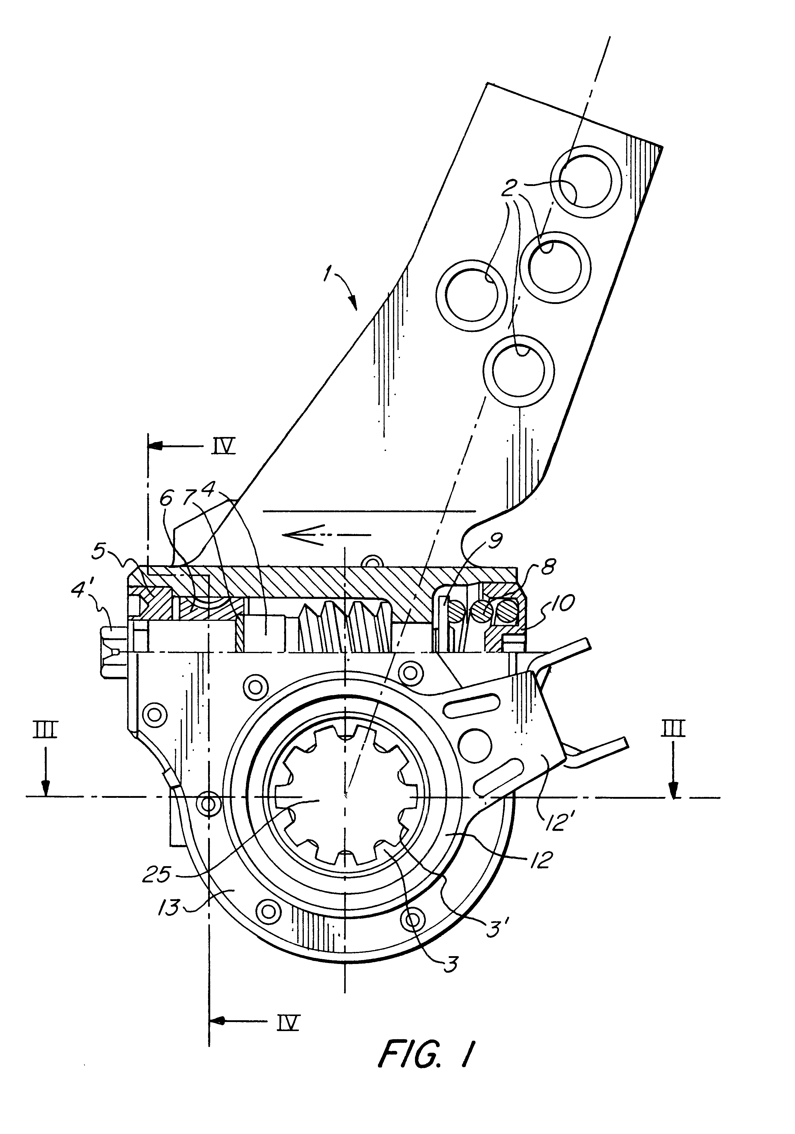
A brake lever of the general type concerned is well known in the art. It constitutes a connection lever in a brake system of a heavy road vehicle between a push rod of a brake cylinder and a splined S-cam shaft of a drum brake arrangement, comprising a brake drum and brake shoes to be pressed apart for braking engagement with the brake drum.

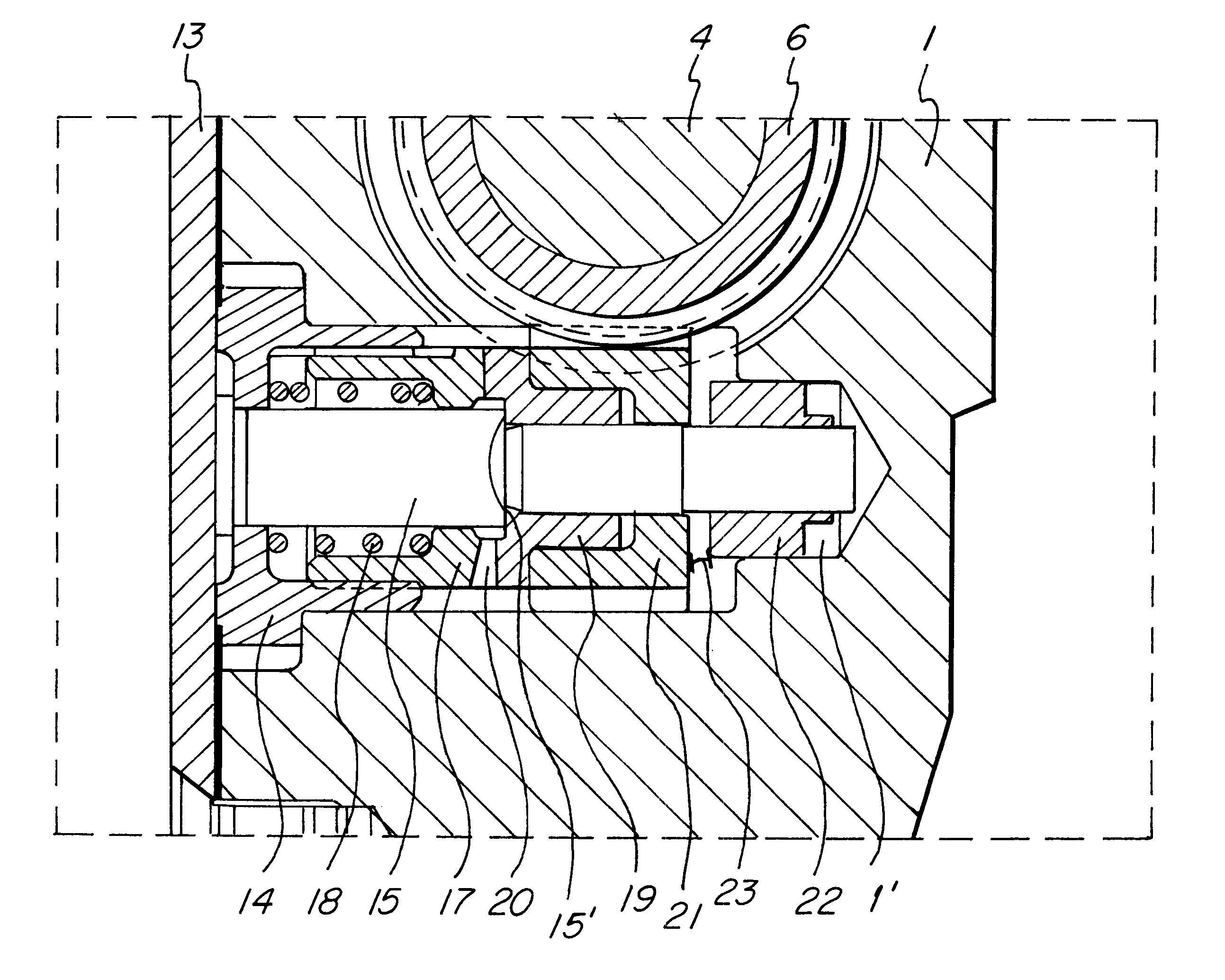
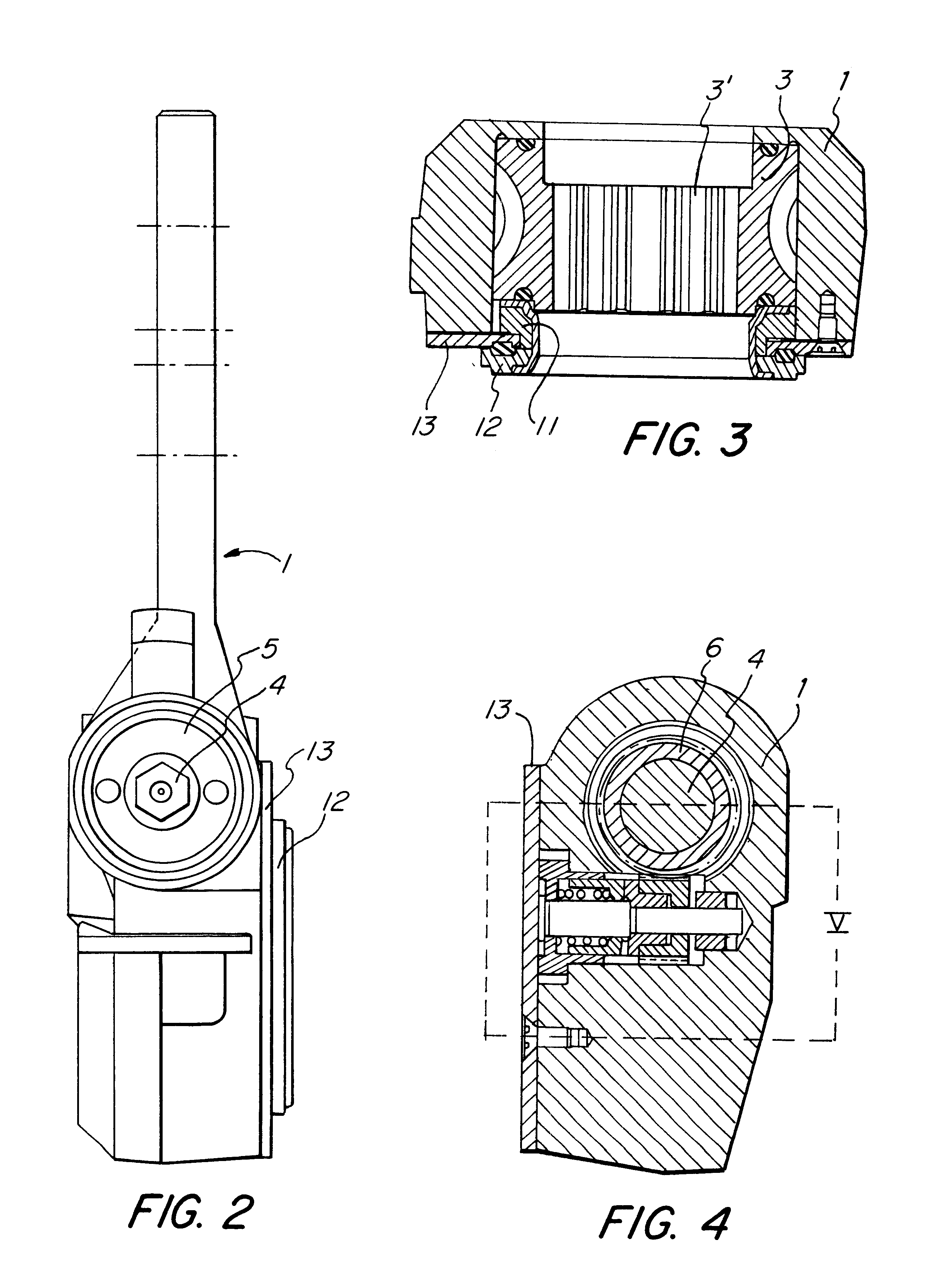
A brake lever housing 1 is at its upper end provided with a number of holes 2, of which one is to be pivotally connected to the brake cylinder push rod (not shown). Towards its opposite end the brake lever is provided with a rotatable worm wheel 3, which has internal splines 3' for attachment to the S-cam shaft (25). Meshing with this worm wheel 3 is a worm screw 4, which is rotatably mounted crosswise in the housing 1.

The end of the worm screw 4 to the left in FIG. 1 extends out of the housing 1, and the worm screw is here provided with a hexagonal tool grip 4' (also visible in FIG. 2) for manual rotation of the screw 4. At this end there is a c...


PUM


Abstract

A brake lever is to be attached to a splined S-cam shaft of an automotive drum brake and to be connected to a brake cylinder push rod. The lever has a control arrangement for transmitting a control movement from a control disc with a reference point to a clutch wheel of the lever mechanism depending on the angular movement of the brake lever. The control disc is in gear engagement with a pinion, and an adjustment screw coaxial with the pinion is in engagement with the clutch wheel. A cylindrical driver is axially but non-rotatably movable in relation to the pinion coaxial therewith and forms a one-way clutch with a unit including the adjustment screw, which is axially movable a distance corresponding to a desired control distance or A-measure for the brake lever, the one-way clutch being spring-biased into engagement.

Description

The present invention relates to a brake lever for attachment to a splined S-cam shaft of an automotive drum brake and connection to a brake cylinder push rod, includinga worm wheel, rotatably mounted in a housing of the brake lever and having internal splines for cooperation with the S-cam shaft, and a worm screw, rotatable in the housing perpendicularly to the worm wheel and meshing therewith, anda control arrangement for transmitting a control movement from a reference point to a clutch wheel, which is rotatable on the worm screw, depending on the angular movement of the brake lever, and which forms a clutch with the worm screw normally held engaged by a strong compression spring,the control arrangement including a control disc, which is rotatable coaxially with the worm wheel and is connected to a control ring having a control arm for establishing the reference point by being attached to a fixed part of a vehicle chassis, a pinion meshing with the toothed periphery of the contro...

Claims


Application Information

Patent Timeline
Patent Type & Authority Patents(United States)
IPC IPC(8): F16D65/60F16D65/38
CPCF16D65/60
Inventor TRUUVERT, JAAN
Owner HALDEX BRAKE PROD AB BOX 501 261 24
Why Eureka
Try Eureka