
Item handler and method for flow through storage

a flow-through storage and item technology, applied in the field of automatic item handling system and methods, can solve the problems of limiting the use of systems requiring hydraulic fluid to function, less modern existing storage facilities, and modification of existing storage facilities, so as to accommodate a more modern and different type of storage system

Inactive Publication Date: 2002-06-25
TYSON FRESH MEATS
View PDF41 Cites 25 Cited by
  • Summary
  • Abstract
  • Description
  • Claims
  • Application Information

AI Technical Summary

Benefits of technology

It is also an object of this invention to maintain the current available floor space between the flow through storage bins in order to assure easy and safe access.
It is also an object of this invention to more reliably automate an existing storage facility with a centrally controlled network of semi autonomous lumping and picking means that make a seamless transport of boxes from production to storage and onto shipping.

Problems solved by technology

Refrigerated meat processing flow through storage facilities are typically maintained at 32.degree. F. or lower, therefore any automated system for storage and retrieval in such a facility must be able to operate under those conditions, which may limit the use of systems requiring hydraulic fluids to function.
However, some less modern existing storage facilities are designed with flow through storage racking.
A second economic reason is that typical automated item handling systems are not designed to meet the unique requirements of a facility that was previously designed to accommodate a flow through storage system, therefore the facility would have to be significantly modified to accommodate a more modern item handling system.
Modification of an existing storage facility, with an existing flow through storage racking system, to accommodate a more modern and different type storage system would be very costly.
The aisles between flow through storage bins in some existing flow through storage facilities are very narrow (approximately 35 in wide) as they were not designed to allot dedicated space for an automated item handling storage system.
Therefore any automated system that requires dedicated floor space for a transport and handling means would further limit the usable floor space between aisles.
Limited floor space on which workers can maneuver inherently makes for hazardous work conditions, causing tripping accidents and accidental collisions that may result in injury.
This function is currently manual and reduces the efficiency of the operation.
A design of this type does not meet the requirements outlined is above for the automation of an existing flow through storage facility.
Typical automated storage handling systems are not easily integrated into such facilities because they either entail large conveyor systems requiring a lot of space or they are remote vehicles that require large aisles and dedicated floor space for a guidance means.
However the apparatus shown in Hainsworth '504 does not have the elements or the functionality to meet the paticular requirements, as outlined above, for automating an existing flow through storage facility.
It will be difficult to maintain a desired flow of handling 60,000 items per day on both the input (lumping) end and the output (picking) end with the Hainsworth design.
Therefore, if the one arm system shown in Hainsworth is used and the arm attempts to remove a box on the top row, it is likely that the box underneath will move due to friction, or possibly the entire skid will move.
There is no means to prevent the lower tier box or the skid from moving.
This would further narrow the useable floor space between flow through bins even when the remote vehicle is not passing through.
However, in the case of a buried wire guidance method, a portion of the floor would have to be torn up in order to install the wire.
Either method is contrary to the requirements outlined above for automating an existing flow through facility because of the extensive modifications and safety impacts.

Method used


Image

  • Item handler and method for flow through storage
  • Item handler and method for flow through storage
  • Item handler and method for flow through storage

Examples


Embodiment Construction

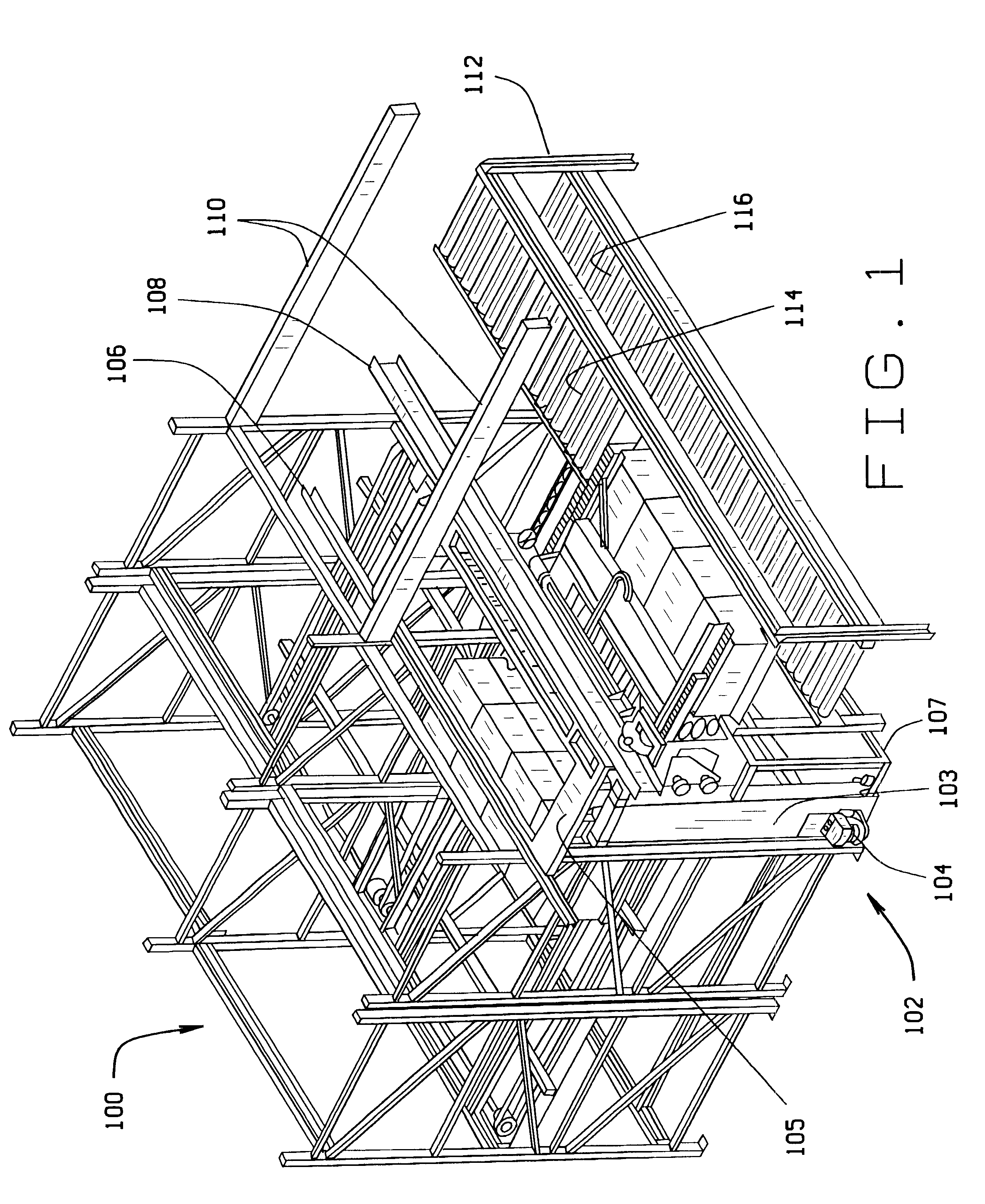
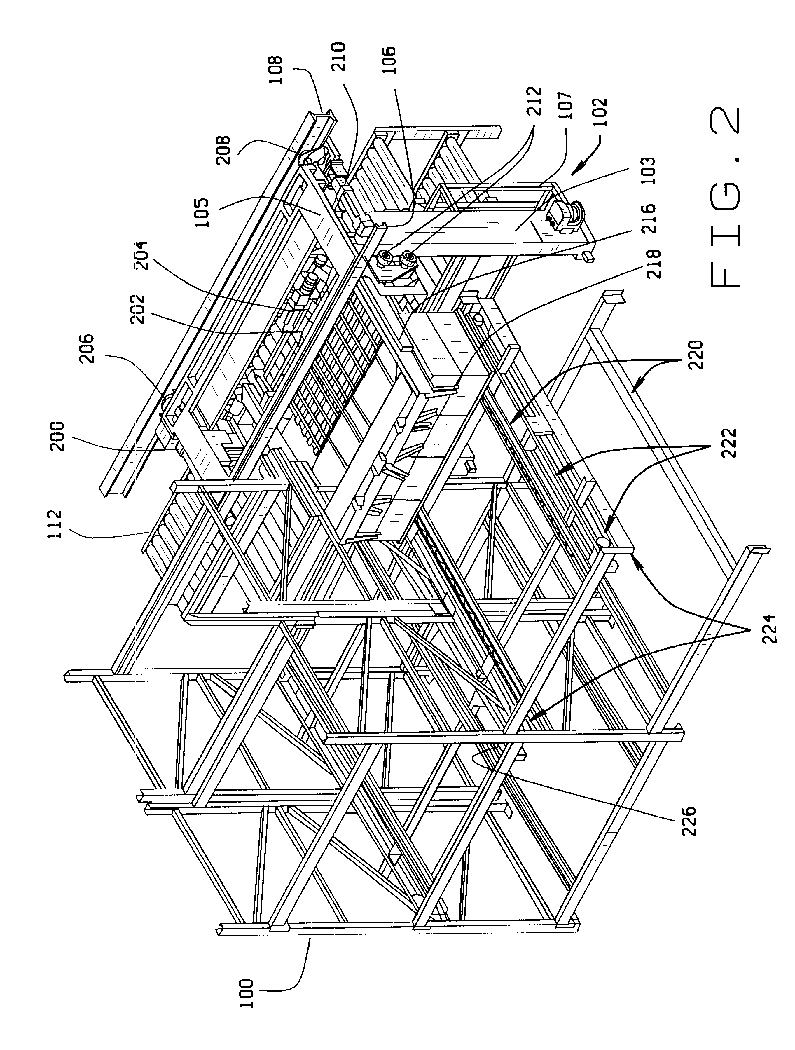
Referring to FIG. 1, a top right front perspective view of a portion of the flow through storage bins 100, the remote vehicle 102, and a portion of the conveyor system 112 is shown on the picking side of the flow through bin. Also shown in this view, is a collision avoidance sensor 104 operatively attached to the remote vehicle 102. The remote vehicle 102 is suspended from the overhead track rails 106 and 108. The remote vehicle is freely suspended having no support underneath. The remote vehicle 102 travels on the track rails 106 and 108 by wheels that are fitted in the track rail slots thereby providing an overhead traction mechanism. Track rail 108 provides power to the remote vehicle. The parallel track rails 106 and 108 are supported by a plurality support members 1110. The basic construction of the remote vehicle frame comprises a pair of upright side frame members 103 having a hollow interior volume to house an elevation mechanism. Only the right side frame member of the pair...


PUM


Abstract

An autonomous remote controlled vehicle for use in the automation of an existing refrigerated flow through storage facility food processing application. The remote vehicle is specifically designed to operate within a network of centrally controlled remote vehicles that are adapted to receive selectable items from production and temporarily store them for later retrieval. The system is adapted to minimize travel time for the remote vehicle and optimize cycle time. The system is specifically adapted to handle cardboard shipping boxes containing meat products.

Description

1. Field of the InventionThis invention relates to an automatic item handling system and methods for handling and transporting items in a facility designed with a flow through storage system. More specifically, the invention relates to automated remote transport and item handling systems that revolve around a network of centrally controlled remote vehicles that handle the storage and retrieval of boxes in a refrigerated flow through storage facility.2. Related ArtThere is a need for an automated item handling system for storing and retrieving items, specifically boxes, that can be implemented in a facility already equipped with a refrigerated flow through storage system and that can be implemented without major modifications to the existing facility. A flow-through storage system is an array of open racks which comprises a plurality of perpendicular crossing beam members that form the rectangular-shaped open storage racks. The term "flow-through" is used because items are stored thr...

Claims


Application Information

Patent Timeline
Patent Type & Authority Patents(United States)
IPC IPC(8): B65G1/04B65G47/82
CPCB65G1/0421B65G47/82B65G1/0435
Inventor FALLIN, LARRY W.SCALIA, BARBARA J.SMITH, RONALD D.DILL, JAMES F.MASON, TIMOTHY J.KOLVEK, EDWARD M.FORTI, STEPHEN N.ESTEY, III, ROLAND H.DOWNER, JAMES R.CANDILORO, CARL BRIANCOURIER, ANDREW S.
Owner TYSON FRESH MEATS
Learn More