Ankle prosthesis

a prosthesis and ankle technology, applied in the field of ankle prosthesis, can solve the problems of increasing the rate of element detachment of the prosthesis, the inability of patients to move freely, and the inability of the three-element ankle prosthesis to completely reproduce the natural physiological shape of the ankle joint, so as to prevent uncontrolled deformation of the implants

Inactive Publication Date: 2002-06-25
EURON FOOT PLATFORM
View PDF10 Cites 179 Cited by
  • Summary
  • Abstract
  • Description
  • Claims
  • Application Information

AI Technical Summary

Benefits of technology

Another object of the invention is to propose a novel ankle prosthesis suitable for improving the conditions under which the prosthesis is implanted and for preventing uncontrolled deformation of the implants after they have been implanted.

Problems solved by technology

Nevertheless, such prostheses make it possible to reproduce only some of the freedoms of movement of the natural ankle joint since the friction surface between the two implants is very different from the ideal physiological shape of the natural ankle joint.
Since this is a constrained system, it leads to the patient's capacity for movement being limited and gives rise to the element making up the prosthesis becoming detached at an increased rate.
Nevertheless, a three-element ankle prosthesis does not completely reproduce the natural physiological shape of the ankle joint.
Consequently, the natural operation of the ankle is not restored by presently-known ankle prostheses.
Pressure cannot be applied while this implant is being implanted since the patient is prone.
Thus, on first pressure against the ground, the tibia implant is pressed against the tibia bone giving rise to relative displacement between the tibia implant and the tibia bone.
This displacement gives rise to high and uncontrolled levels of mechanical stress at the locking studs and the housings for receiving them, which can give rise to deformation or even to a risk of separation.

Method used


Image

  • Ankle prosthesis
  • Ankle prosthesis
  • Ankle prosthesis

Examples


Embodiment Construction

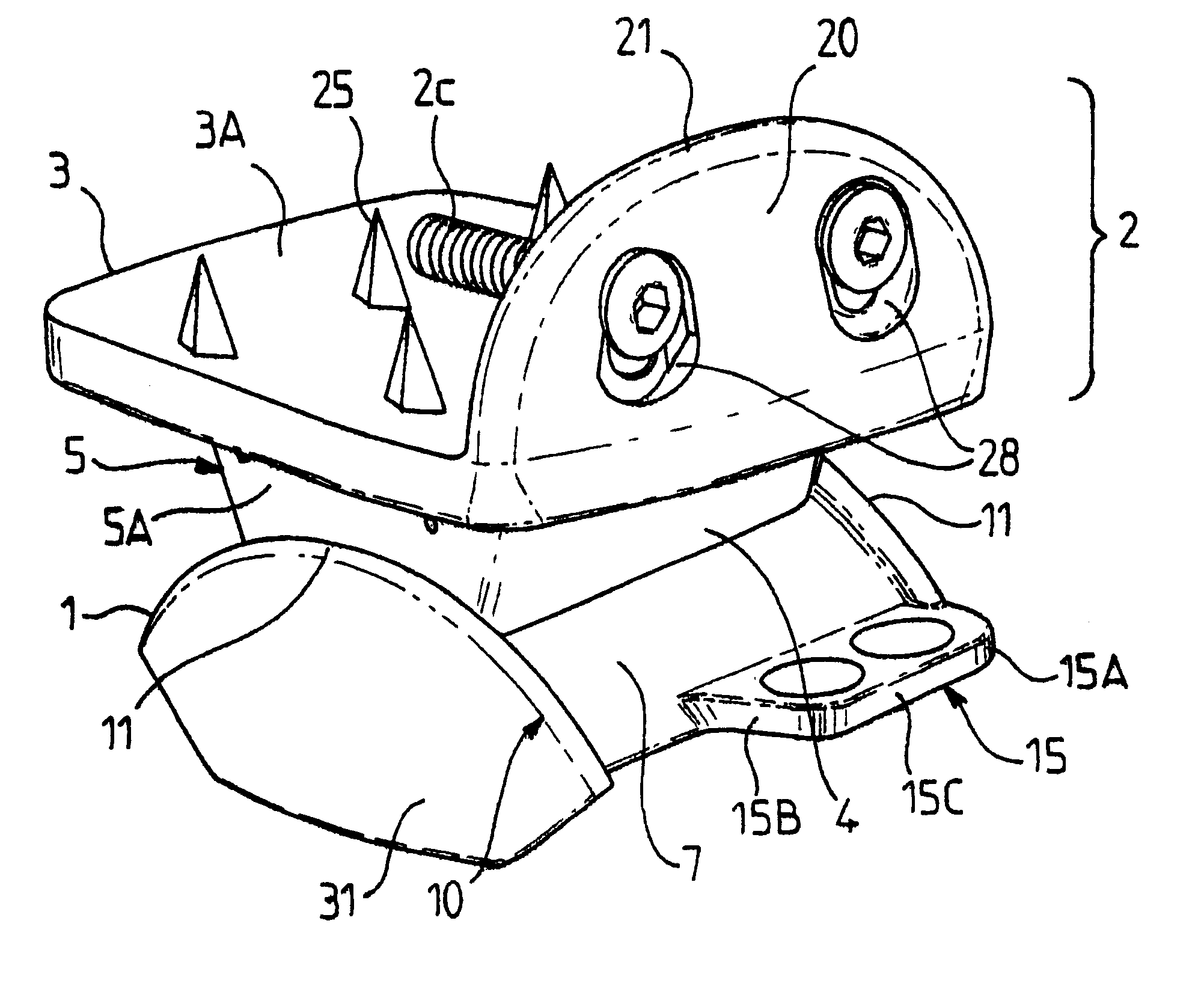
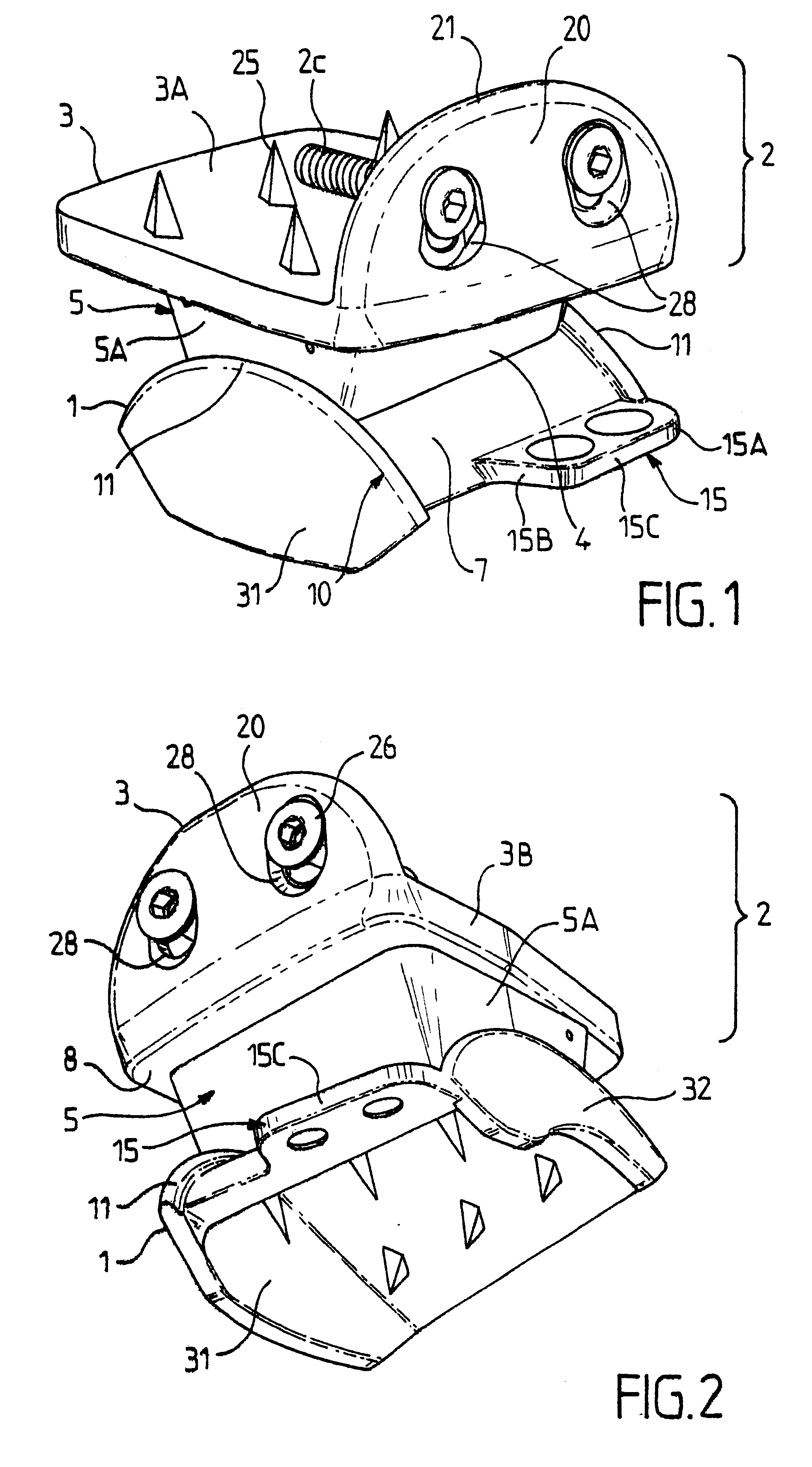
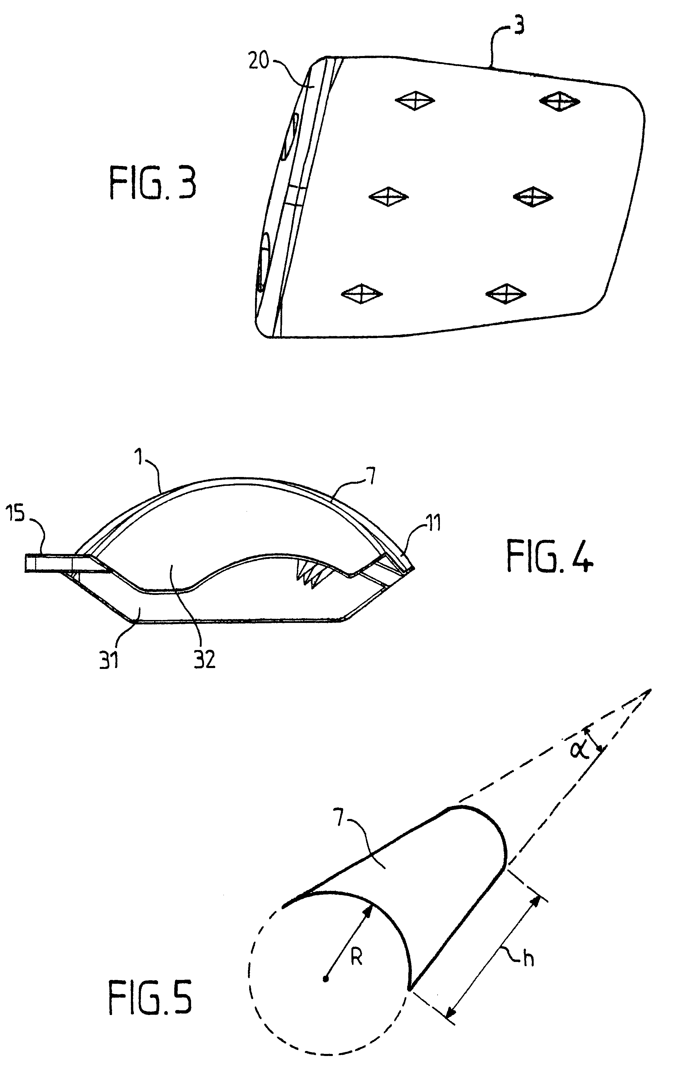
FIGS. 1 to 8 show an ankle prosthesis in accordance with the invention comprising a talus implant 1 designed to be implanted in or on the talus of the ankle joint of a patient. The ankle prosthesis in accordance with the invention also comprises a top element 2 including a tibia implant 3 for implanting in or on the base of the tibia of a patient.

The top element 2 and the talus implant 1 are mounted to move relative to each other by friction on a contact interface 4 so as to allow the ankle to move.

In the embodiment shown in FIGS. 1 and 2, the top element 2 further includes an intermediate implant 5 interposed between the tibia implant 3 and the talus implant 1, said intermediate implant 5 being in free frictional contact with the other two implants via each of two opposite faces.

Thus, in the description below, reference is constantly made to an ankle prosthesis comprising a set of three implants, namely: a talus implant 1; a tibia implant 3; and an intermediate implant 5; it being ...


PUM


Abstract

The invention provides an ankle prosthesis for use in the field of orthopedic prostheses comprising a talus implant for implanting in or on the talus and a top element including a tibia implant for implanting in or on the base of the tibia. The top element and the talus implant being mounted to move relative to each other by friction on a contact interface so as to allow the ankle to move. The contact interface presents a friction surface that can be considered as being a fraction of a substantially frustoconical surface. When implanted, the substantially frustoconical surface is oriented so that its larger radius portion is directed substantially towards the outside of the ankle.

Description

The present invention relates to the technical field of ankle prostheses for performing orthopedic treatment of the ankle joint by implementing prosthetic elements for restoring the anatomy of the ankle joint.The present invention relates to an ankle prosthesis comprising a talus implant designed to be implanted in or on the talus or "ankle bone", and a top element including a tibia implant for implanting in or on the base of the tibia, said top element and the talus implant being mounted to move relative to each other with friction at a contact interface to allow movement of the ankle.It is already known to use ankle prostheses after traumatic injury that has led to partial or total damage to the joint space of the ankle, in order to restore the joint anatomy of the ankle, at least in part.Thus, ankle prostheses are already known comprising two implants, namely a talus implant for implanting in or on the talus, and a tibia implant for implanting in or on the base of the tibia. Thes...

Claims


Application Information

Patent Timeline
Patent Type & Authority Patents(United States)
IPC IPC(8): A61F2/42A61B17/68A61B17/86A61F2/00A61F2/30
CPCA61F2/4202A61B17/86A61F2002/30578A61F2002/30604A61F2002/30777A61F2002/30785A61F2310/00179A61F2002/30892A61F2002/30906A61F2002/4205A61F2002/4207A61F2310/00029A61F2002/30843
Inventor PERICE, RAMON VILADOTDEREYMAEKER, GRETADIEBOLD, PATRICE FRAN.ANG.OISHINTERMANN, BEAT
Owner EURON FOOT PLATFORM
Why Eureka
Try Eureka