Rinsing tank with ultra clean liquid

a technology of ultra-clean liquid and rinsing tank, which is applied in the direction of electrostatic cleaning, electrical equipment, semiconductor/solid-state device manufacturing, etc., can solve the problems of reducing the cleaning effect, requiring a large consumption of deionized water, and affecting the cleaning characteristics, etc., and achieves the effect of small liquid consumption

Inactive Publication Date: 2002-07-02
VACO MICROTECH
View PDF11 Cites 10 Cited by
  • Summary
  • Abstract
  • Description
  • Claims
  • Application Information

AI Technical Summary

Benefits of technology

The object of the invention is to achieve rinsing tank for rinsing with an ultra clean liquid enabling optimum rinsing of the objects contained in the tank to be obtained with a small consumption of liquid.

Problems solved by technology

The turbulence effect created in the rinsing chamber when the water rises disturbs the uniform circulation of the water to the detriment of the cleaning characteristics.
This type of tank also requires a large consumption of deionized water.

Method used


Image

  • Rinsing tank with ultra clean liquid
  • Rinsing tank with ultra clean liquid
  • Rinsing tank with ultra clean liquid

Examples


Embodiment Construction

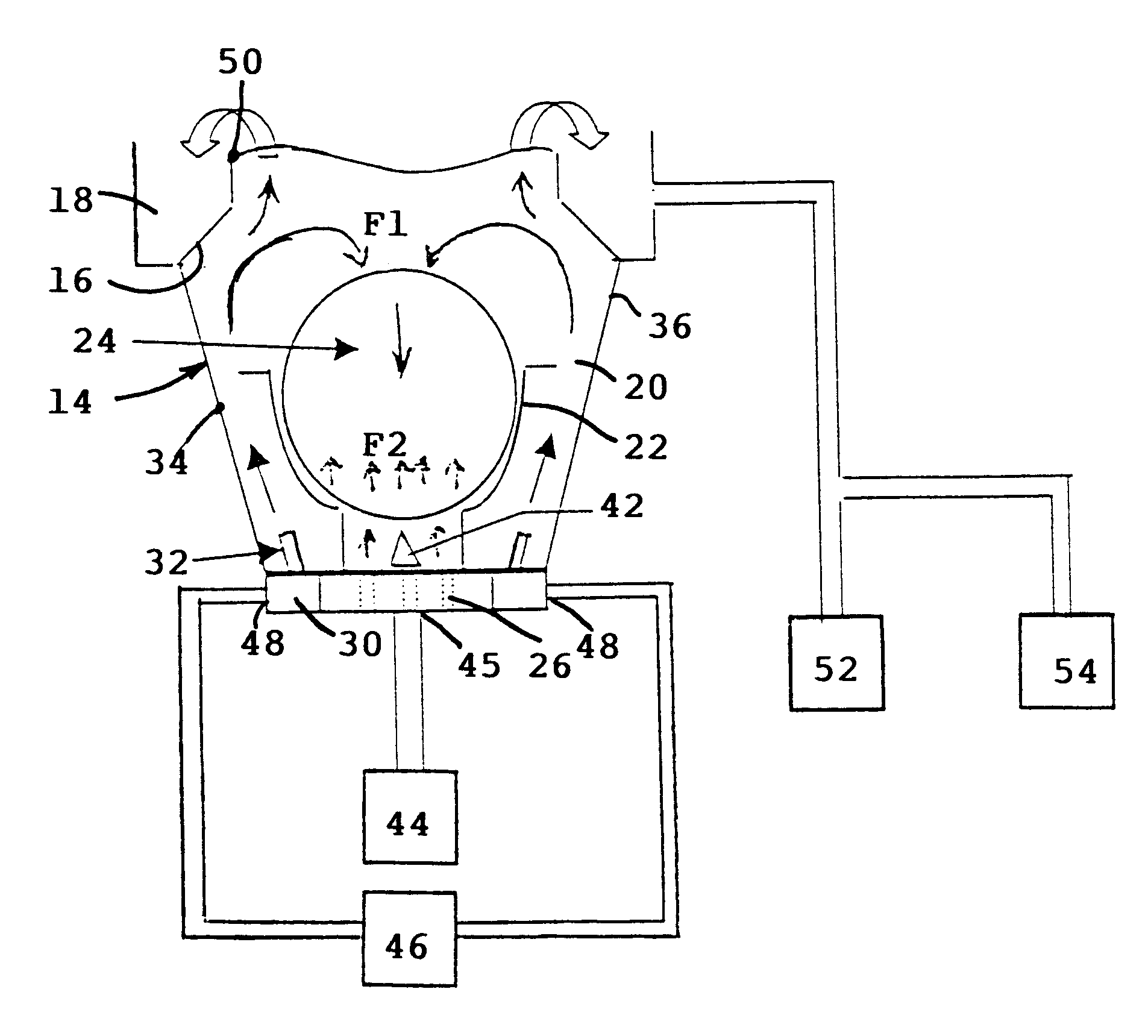
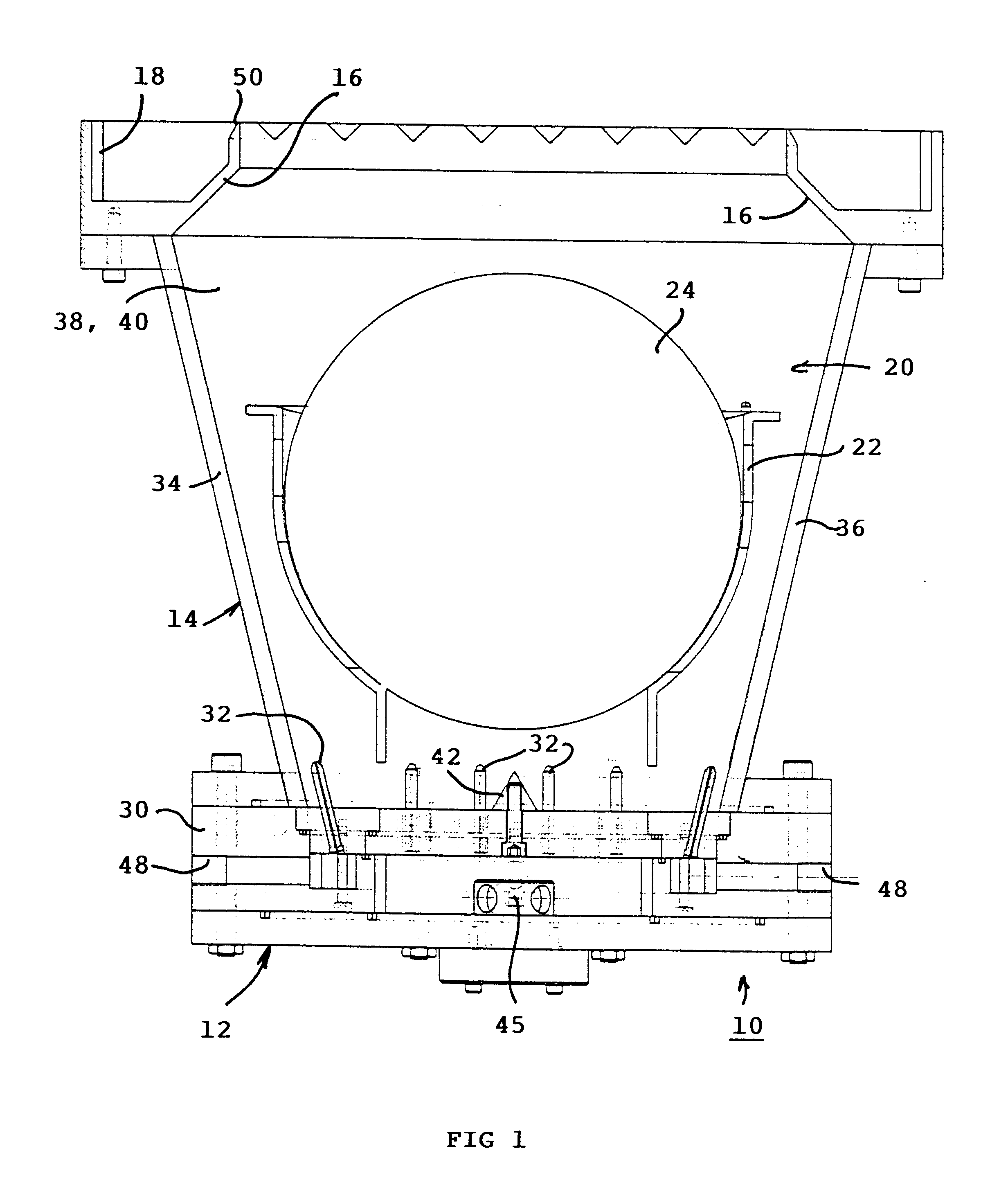
With reference to FIGS. 1 to 5, the rinsing tank 10 comprises at its base a diffusing device 12 for diffusing an ultra clean liquid, for example deionized water, to which an enclosure 14 is connected equipped at its top part with a deflector 16 and an overflow spout 18. Inside the rinsing chamber 20 confined by the enclosure 14 there is located a container 22 accommodating substrates 24 to be rinsed.

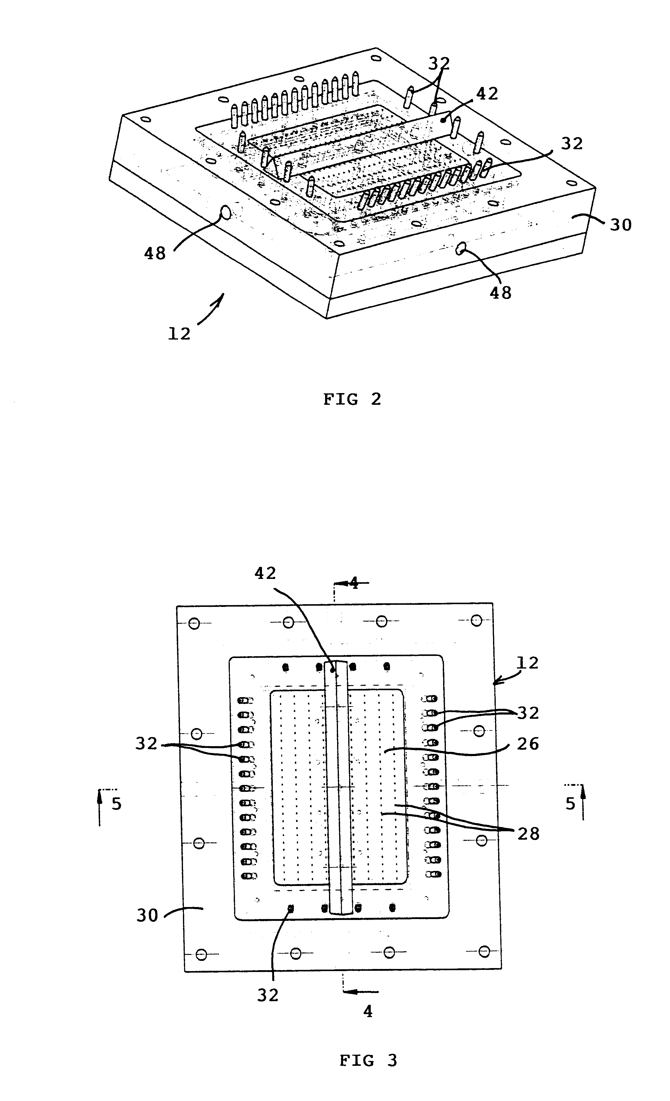
The water diffusing device 12 is composed of a base plate 26 perforated by several rows of holes 28 placed under the container 22, and of a peripheral flange 30 bearing a plurality of water projection nozzles 32. The enclosure 14 comprises two side faces 34, 36 inclined at a predetermined angle and joined to two parallel vertical faces 38, 40. The nozzles 32 are staggered along the flange 30 extending in the direction of the four faces 34, 36, 38, 40 of the tank. Depending on the type of rinsing chamber, the nozzles 32 situated on the side where the faces 38, 40 are located can be elimin...


PUM


Abstract

A rinsing tank for rinsing with ultra clean liquid comprises a rinsing chamber confined by an enclosure equipped at the bottom part with a diffusing device with a perforated base plate connected to a first pressurized cleaning liquid supply system, and with an overflow spout at the upper part. The periphery of the perforated base plate of the diffusing device is equipped with a plurality of projection nozzles or injectors connected to a second pressurized liquid supply system. The rising flow coming from the injectors causes a downward circulation of liquid designed to remove the contaminants and particles present at the surface of the substrates. The hydraulic piston effect generated by the first supply system of the base plate forces the rinsing liquid upwards towards the overflow spout. The tank may be used for rinsing of silicon, quartz, germanium, glass, etc. substrates commonly used in the semi-conductors, micro-systems and flat screen industries.

Description

The invention relates to a rinsing tank for rinsing with ultra clean liquid comprising a rinsing chamber confined by an enclosure equipped at the bottom part with a diffusing device with a perforated base plate connected to a first pressurized liquid supply system, and with an overflow spout at the upper part to receive the rinsing liquid charged with particles or contaminants removed from the objects to be rinsed.STATE OF THE TECHNIQUEA first type of known rinsing tank operates by overflow due to the presence of an overflow pipe at the top part of the tank. The rinsing chamber is filled with ultra clean deionized water up to the level of the overflow pipe. Filling is performed by means of a water inlet pipe situated in the central part of the bottom of the tank. The water flows out by overflowing into the overflow pipe and is removed by an outlet pipe. Rinsing of the substrates contained in the container inside the rinsing chamber is achieved by a simple filling effect of the tank....

Claims


Application Information

Patent Timeline
Patent Type & Authority Patents(United States)
IPC IPC(8): B08B3/10B08B3/12H01L21/304H01L21/306
CPCB08B3/102H01L21/67051H01L21/67057B08B3/048Y10S134/902H01L21/304
Inventor ORAVEC, VICTORIA
Owner VACO MICROTECH
Why Eureka
Try Eureka