Measuring equipment with a safety apparatus for the transport and the assembly of the measuring equipment

a safety apparatus and measuring equipment technology, applied in the field of measuring systems, can solve the problems of insufficient guided on the support body, inability to fix the position of the support body on the one hand, and difficulty in removing the securing device from the measuring system

Inactive Publication Date: 2002-07-09
DR JOHANNES HEIDENHAIN GMBH
View PDF31 Cites 22 Cited by
  • Summary
  • Abstract
  • Description
  • Claims
  • Application Information

AI Technical Summary

Benefits of technology

It an object of the present invention to create a measuring system for determining the position of two components which are movable in relation to each other, having a securing device for the transport and mounting of the measuring system, wherein the support body as well as the scanning device of the measuring system can be fixed in place essentially without play in a defined relative position, and wherein the securing device can be removed in the easiest possible manner at the termination of mounting of the measuring system.

Problems solved by technology

The known securing device has the disadvantage that it merely permits a fixing in place, which involves play, of the mounting base, and therefore also of the scanning device, on the support body since, in order to be able to remove the securing device again from the support body at the termination of mounting the measuring system on a machine tool, the resilient tongue of the securing device must be designed to be sufficiently elastic.
This securing device has the disadvantage that it is only insufficiently guided on the support body.
Because of its deformability, this locking device is therefore not suited to fix the position of the support body on the one hand, and of the scanning device on the other hand, in a manner which is free of play to a great extent.
Because of this engagement it is difficult to remove the securing device from the measuring system.

Method used


Image

  • Measuring equipment with a safety apparatus for the transport and the assembly of the measuring equipment
  • Measuring equipment with a safety apparatus for the transport and the assembly of the measuring equipment
  • Measuring equipment with a safety apparatus for the transport and the assembly of the measuring equipment

Examples


Embodiment Construction

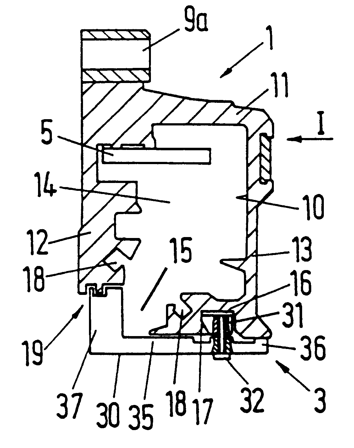
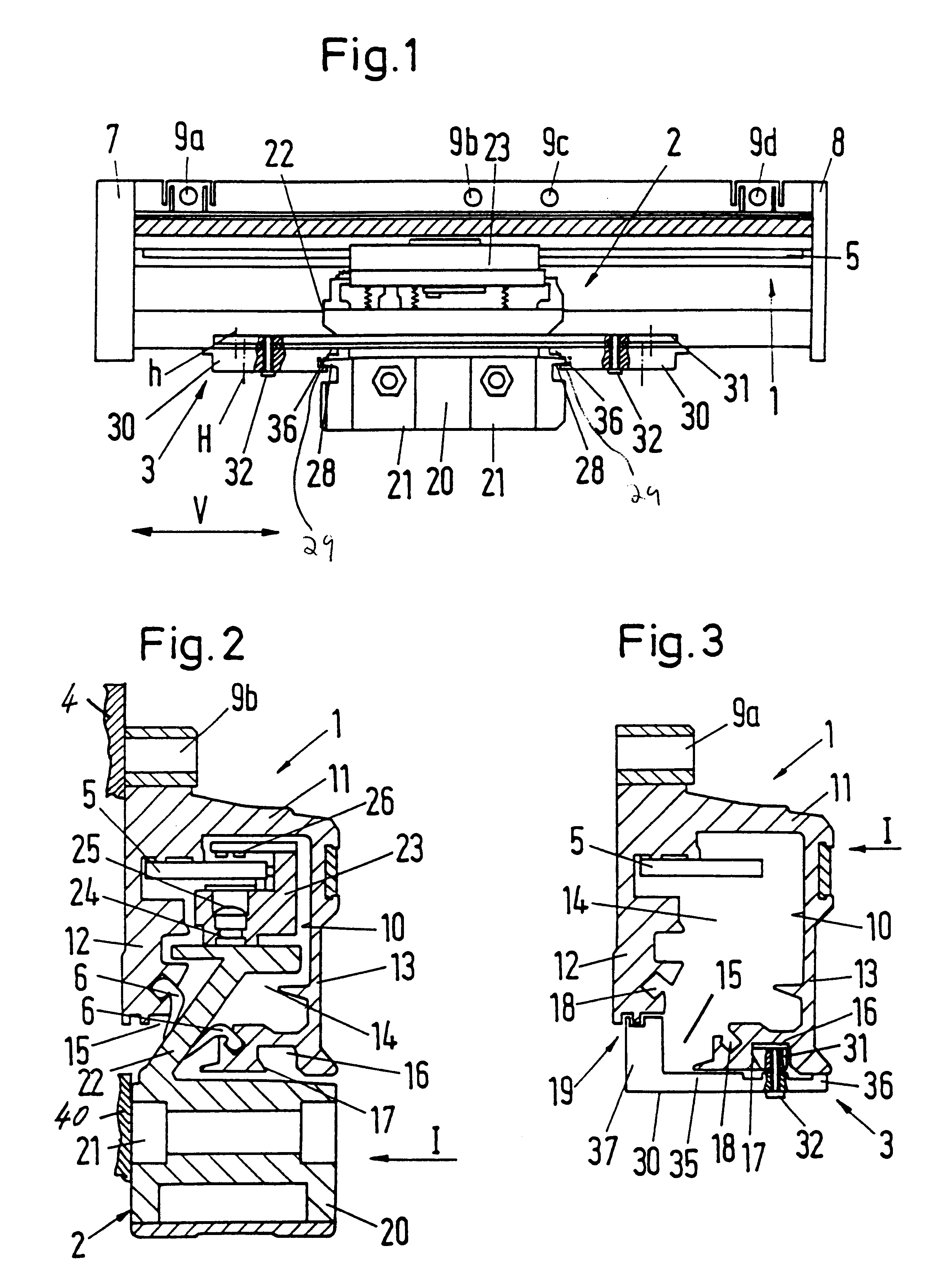
A measuring system for determining the position of two components 4, 40 of a machine tool, which are movable in relation to each other, is represented in FIGS. 1-3, and includes a support body 1, a scanning device 2 and a securing device 3, by which the scanning device 2 can be maintained in a defined prescribed position on the support body 1. Here, the leg 13, which is in front in the viewing direction I (see FIGS. 2 and 3), is not represented in order to clear the view of the interior of the support body 1.

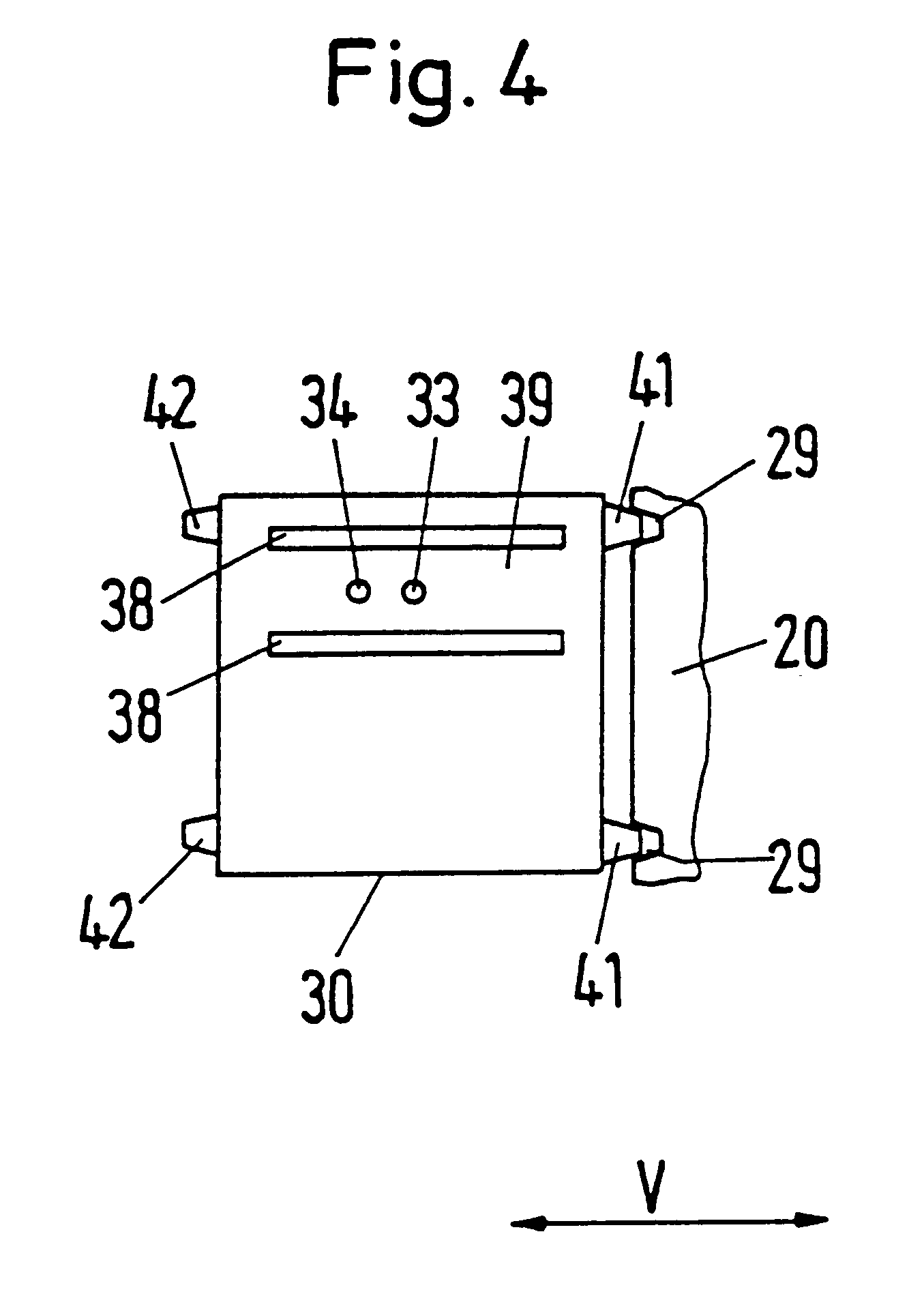
FIGS. 2 and 3 respectively represent a cross section through the measuring system in accordance with FIG. 1 in the area of a mounting opening 9b, or respectively a mounting opening 9a. For reasons of clarity, here only the components of the scanning device 2 are represented in FIG. 2, and the components of the securing device 3 in FIG. 3, besides the components of the support body 1.

In accordance with FIGS. 1 and 2, the support body 1 includes a longitudinally extending hollow p...


PUM


Abstract

A measuring system for determining the position of two machine components that are movable in relation to each other, having a measuring graduation extending in a measuring direction, a support body supporting the measuring graduation, a scanning device scanning the measuring graduation, a mounting base for fastening the scanning device on one of the components, and a securing device for fixing the mounting bas in place in a prescribed position with respect to the support body. The securing device includes a base body that is supported on at least two areas of the support body that are spaced apart from each other with respect to the measuring direction and a guide element. A guide track is provided in the support body, wherein the guide element interlockingly engages the guide element and in which the guide element can be clamped in place in that the guide element is displaced in relation to the base body by a connecting element.

Description

Applicants claim, under 35 U.S.C. .sctn. 119, the benefit of priority of the filing date of Apr. 16, 1999 of a German patent application, copy attached, Ser. No. 199, 18 654,5, filed on the aforementioned date, the entire contents of which is incorporated herein by reference.1. Field of the InventionThe invention relates to a measuring system for determining the position of two machine components that are movable in relation to each other, having a securing device for transport and mounting.2. Discussion of Related ArtA measuring system of the type mentioned at the outset and having a securing device is known from DE 30 20 003 C2. Here, a measuring system includes a longitudinally extending measuring graduation, a support body supporting the measuring graduation, a scanning device scanning the measuring graduation, which is guided at a defined distance from the measuring graduation, and a mounting base connected with the scanning device for fastening the scanning device on one of th...

Claims


Application Information

Patent Timeline
Patent Type & Authority Patents(United States)
IPC IPC(8): G01D5/26G01D5/347
CPCG01D5/34746
Inventor MULLER, JOSEFSCHRODER, WILHELM
Owner DR JOHANNES HEIDENHAIN GMBH
Why Eureka
Try Eureka