
Ascertaining information for compensating an unbalance of elastic rotors

a technology of elastic rotors and information, applied in the direction of static/dynamic balance measurement, vibration measurement in solids, instruments, etc., can solve the problems of infinitely large bending or permanent deformation of the rotor, unbalance effect, internal bending moments remain in the rotor, etc., to avoid the computer processing of these system data

Inactive Publication Date: 2002-07-09
SCHENCK ROTEC GMBH
View PDF16 Cites 23 Cited by
  • Summary
  • Abstract
  • Description
  • Claims
  • Application Information

AI Technical Summary

Benefits of technology

to provide a method that permits a rapid balancing of elastic rotors based on values measured on the rotor and on calculated informations necessary for the balancing; and
The inventor has recognized that it is possible to completely determine all influence coefficients that are required for a balancing operation also referred to herein as unbalance compensation if the rotor in question is excited by a force application in several compensation or balancing planes. By taking into account influence coefficients related to force excitation which are then transformed into unbalance influence coefficients by calculation and by a single unbalance run made to measure unbalance effects one can ascertain the unbalance compensating values without the need for taking into account specific system characteristics such as rotor specific data and bearing specific data. By using these calculated unbalance influence coefficients a balancing operation or unbalance compensation can be performed in a most simple manner by determining the required unbalance compensating weights on the basis of said coefficients and a single unbalance run.
The invention makes it possible for the first time to ascertain the influence coefficients for obtaining or calculating balancing weights by simple measurements without first ascertaining data for the entire balancing system such as the above rotor and bearing specific data. Computer processing of these system data is also avoided. The influence coefficients are simply measured, processed in a computer for transformation and then used for ascertaining the balancing weights required for a balancing operation or unbalance compensation. A special advantage of the invention is seen in that the force application for exciting the rotor can be made either while the rotor is at a standstill or while the rotor rotates. Another advantage is seen in that several test runs with different testing weights applied to the rotor are no longer necessary.

Problems solved by technology

As a result, internal bending moments remain in the rotor due to centrifugal forces produced by individual unbalances.
In connection with elastic rotors, such internal bending moments can cause forces that rise with the square of the r.p.m., thereby leading to unpermissibly large deformations which in turn cause unbalance effects.
This fact can cause a dangerous situation, especially when the operational r.p.m. approaches a bending critical r.p.m. which could without damping cause an infinitely large bending or a permanent deformation of the rotor.
Such unbalance forces involve rigid body forces and forces caused by the wave elastic deformation or deflection of the rotor.
Thus, at least four unbalance measuring sequences are required when considering the first critical r.p.m. of the rotor to be balanced.
Such a method has the disadvantage that first a conventional rigid body compensation must be performed and only thereafter it is possible to eliminate modal unbalances by additional measuring and compensating processes.

Method used


Image

  • Ascertaining information for compensating an unbalance of elastic rotors
  • Ascertaining information for compensating an unbalance of elastic rotors
  • Ascertaining information for compensating an unbalance of elastic rotors

Examples


Embodiment Construction

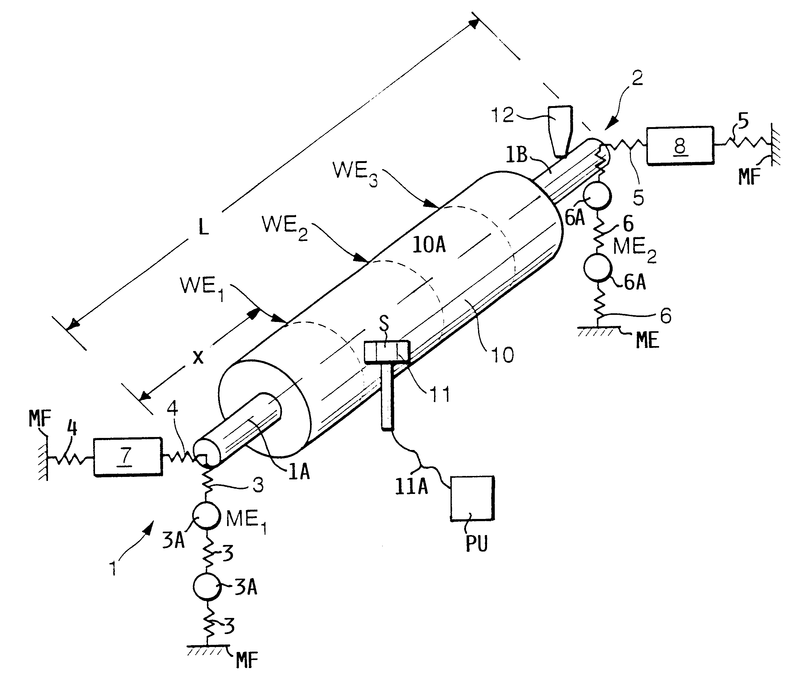
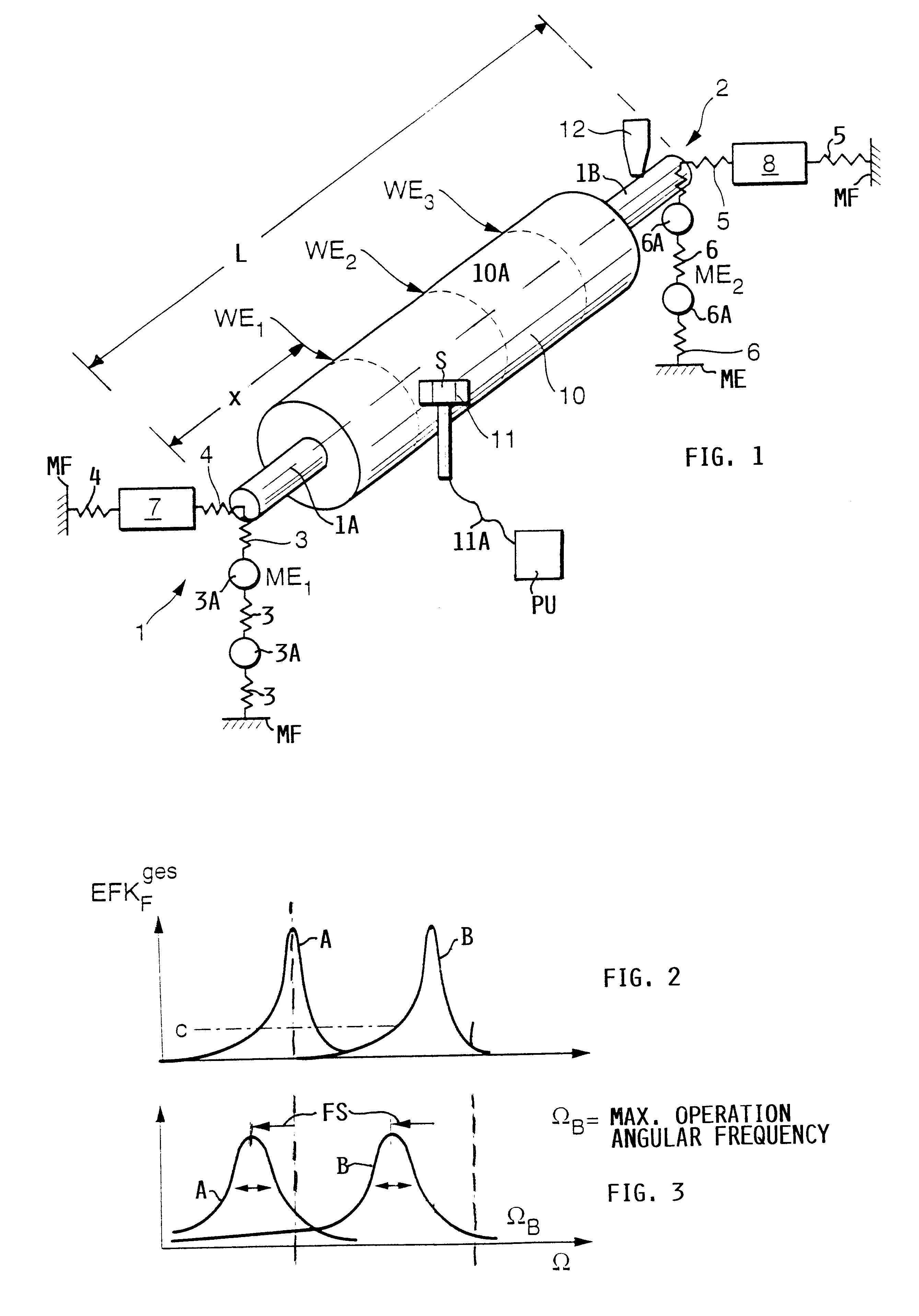
FIG. 1 shows schematically a system for measuring the unbalances of a rotor 10. Details of the rotor support and its drive are not part of the invention. However, such details are shown in "International Standard ISO#1925, Third Edition "Mechanical Vibration-Balancing-Vocabulary", pages 14, 15, 19, 20, 24, 25 and 26 incorporated herein by reference. A first mounting 1 holds or supports one end 1A of a rotor shaft. A second mounting 2 holds the other end 1B of the shaft of the rotor 10. These supports 1 and 2 are, for example, constructed as conventional rocking bridge bearings as used in force or displacement measuring balancing machines. These supports or bearings 1 and 2 are supported against a machine frame MF. The first support 1 is formed by springs 3 and masses 3A providing a vertical support in a first measuring plane ME.sub.1. Springs 4 provide a horizontal support in the plane ME.sub.1. The springs 3 and 4 and the masses 3A form a first spring mass system, whereas the symbo...


PUM


Abstract

Rotors, especially elastic rotors, are balanced by measuring unbalance values which provide information regarding the size, or rather the weight of balancing weights and the angular location where these balancing weights are to be secured to the rotor. For obtaining balancing weights an excitation force is applied to the rotor which is at a standstill or which may, but does not have to, rotate when the excitation force is applied by a hammer (11), equipped with a sensor (S) and an output (11A) to provide excitation force spectra. Further sensors (7, 8) are positioned in bearing planes (ME1, ME2) and provide response force spectra. The excitation force spectra and the response force spectra due to the rotating unbalanced rotor are then processed to obtain the unbalance compensating values required for the balancing operation.

Description

PRIORITY CLAIMThis application is based on and claims the priority under 35 U.S.C. .sctn.119 of German Patent Application 198 11 101.0, filed on Mar. 13, 1998, the entire disclosure of which is incorporated herein by reference.The invention relates to balancing of flexible rotors, more specifically, to ascertaining unbalance compensating values that represent an unbalance of an elastic rotor and are required for an unbalance compensation of the elastic rotor. The invention further relates to ascertaining coefficients which have an influence on the balancing of unbalanced elastic rotors, which normally have a rigid behavior in a low r.p.m. range.BACKGROUND INFORMATIONIn order to balance rigid rotors having a simple cylindrical shape and rotating at a low r.p.m., it is customary to measure the resulting unbalance of all individual unbalances generally in the left bearing or support plane and in the right bearing or support plane. If a balancing is necessary, the measured resultant of ...

Claims


Application Information

Patent Timeline
IPC IPC(8): G01M1/22G01M1/24G01M1/00G01M1/16G01M1/20
CPCG01M1/22G01M1/24
Inventor WIESE, DIETMAR
Owner SCHENCK ROTEC GMBH
Learn More