Electric contactor housing
- Summary
- Abstract
- Description
- Claims
- Application Information
AI Technical Summary
Benefits of technology
Problems solved by technology
Method used
Image
Examples
Embodiment Construction
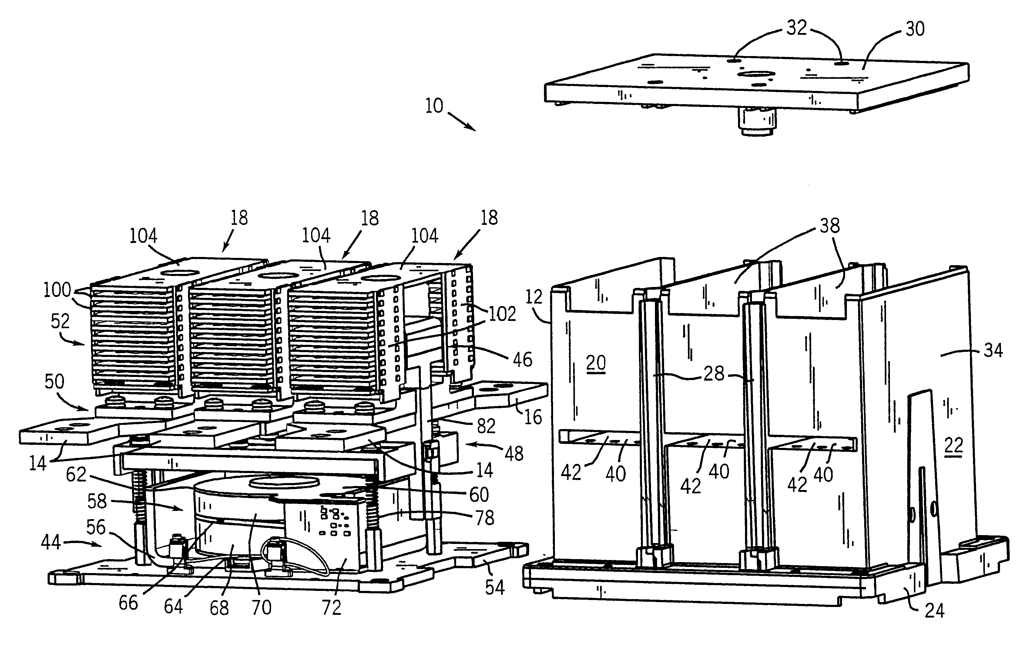
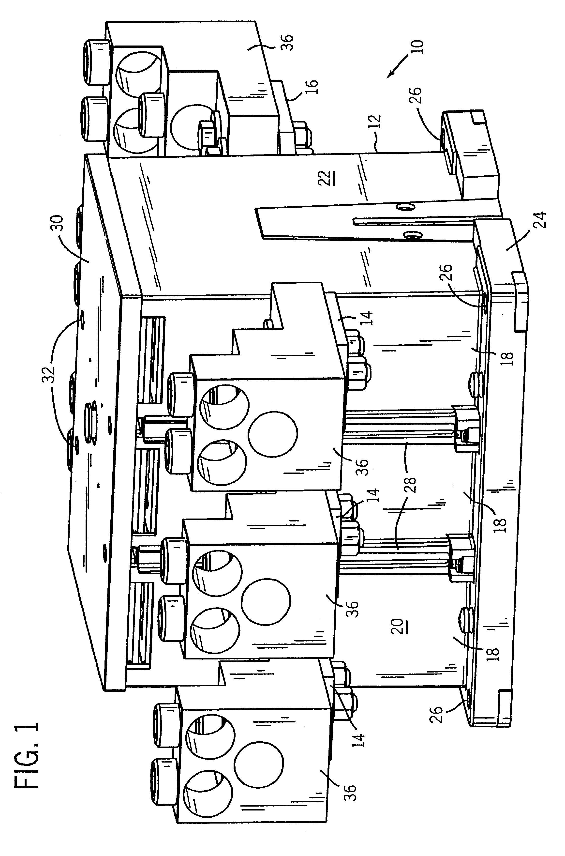
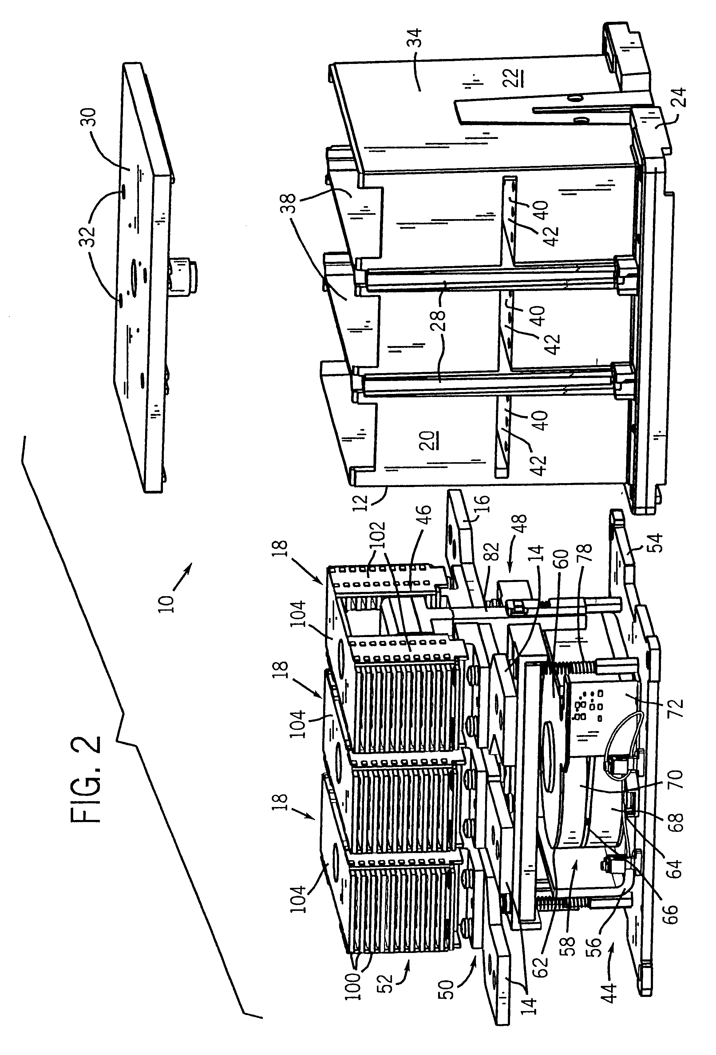
Turning now to the drawings, and referring first to FIG. 1, an electrical contactor 10 is illustrated in the form of a three-phase contactor for completing electrical current carrying paths for three separate phases of electrical power. Contactor 10 includes a housing 12 from which input or line terminals 14 and output or load terminals 16 extend. Contactor 10 is divided into three separate phase sections 18, with a pair of input and output terminals being associated with each phase section. Housing 12 includes end panels 20 and side walls 22 enclosing internal components as described more fully below. Input and output terminals 14 and 16 extend from end panels 20 for connection to power supply and load circuitry. Housing 12 further includes a lower securement flange 24 having apertures 26 formed therein for securing the contactor to a support base, such as in a conventional industrial enclosure (not shown). Ribs 28 are formed on end panels 20 to aid in electrically isolating phase ...
PUM
 Abstract
Description
Claims
Application Information
 - R&D
- Intellectual Property
- Life Sciences
- Materials
- Tech Scout
- Unparalleled Data Quality
- Higher Quality Content
- 60% Fewer Hallucinations
Browse by: Latest US Patents, China's latest patents, Technical Efficacy Thesaurus, Application Domain, Technology Topic, Popular Technical Reports.
© 2025 PatSnap. All rights reserved.Legal|Privacy policy|Modern Slavery Act Transparency Statement|Sitemap|About US| Contact US: help@patsnap.com


