Designing tool for designing access communication network, designing method thereof, and record medium

a technology of access communication network and designing tool, which is applied in the direction of data switching network, frequency-division multiplex, instruments, etc., can solve the problems that the existing communication facilities and civil construction facilities of a conventional narrow band access communication network cannot be re-used, the designer cannot freely define the alternative deployment position of the facility, and the designer cannot edit and define existing facilities

Inactive Publication Date: 2002-07-09
NEC CORP
View PDF13 Cites 24 Cited by
  • Summary
  • Abstract
  • Description
  • Claims
  • Application Information

AI Technical Summary

Problems solved by technology

Thus, when an access communication network is automatically designed with such a system, the designer cannot edit and define existing facilities.
However, under such limited conditions, when a broad band access communication network is designed, existing communication facilities and civil construction facilities of a conventional narrow band access communication network cannot be re-used.
In addition, the designer cannot freely define facility deployment position alternatives.
Before the system automatically designs an access communication network, the designer cannot designate facility deployment positions.
Moreover, the system cannot automatically design an additional network using a blank capacity with the existing facilities.
However, the above-described art reference has the following problems.
As a first problem, even if a route at the minimum cost is obtained considering the binding of cables, the route contains many bends.
Thus, such a route may not be suitable...

Method used


Image

  • Designing tool for designing access communication network, designing method thereof, and record medium
  • Designing tool for designing access communication network, designing method thereof, and record medium
  • Designing tool for designing access communication network, designing method thereof, and record medium

Examples


embodiment

(Description of Operation of Embodiment)

FIG. 6 is a schematic diagram showing a data flow for explaining the operation of the system according to an embodiment of the present invention. Marks in the FIG. 6 coincide with the marks in the FIG. 5, for example, G1 to G9, S1 to S10 and D1 to D5.

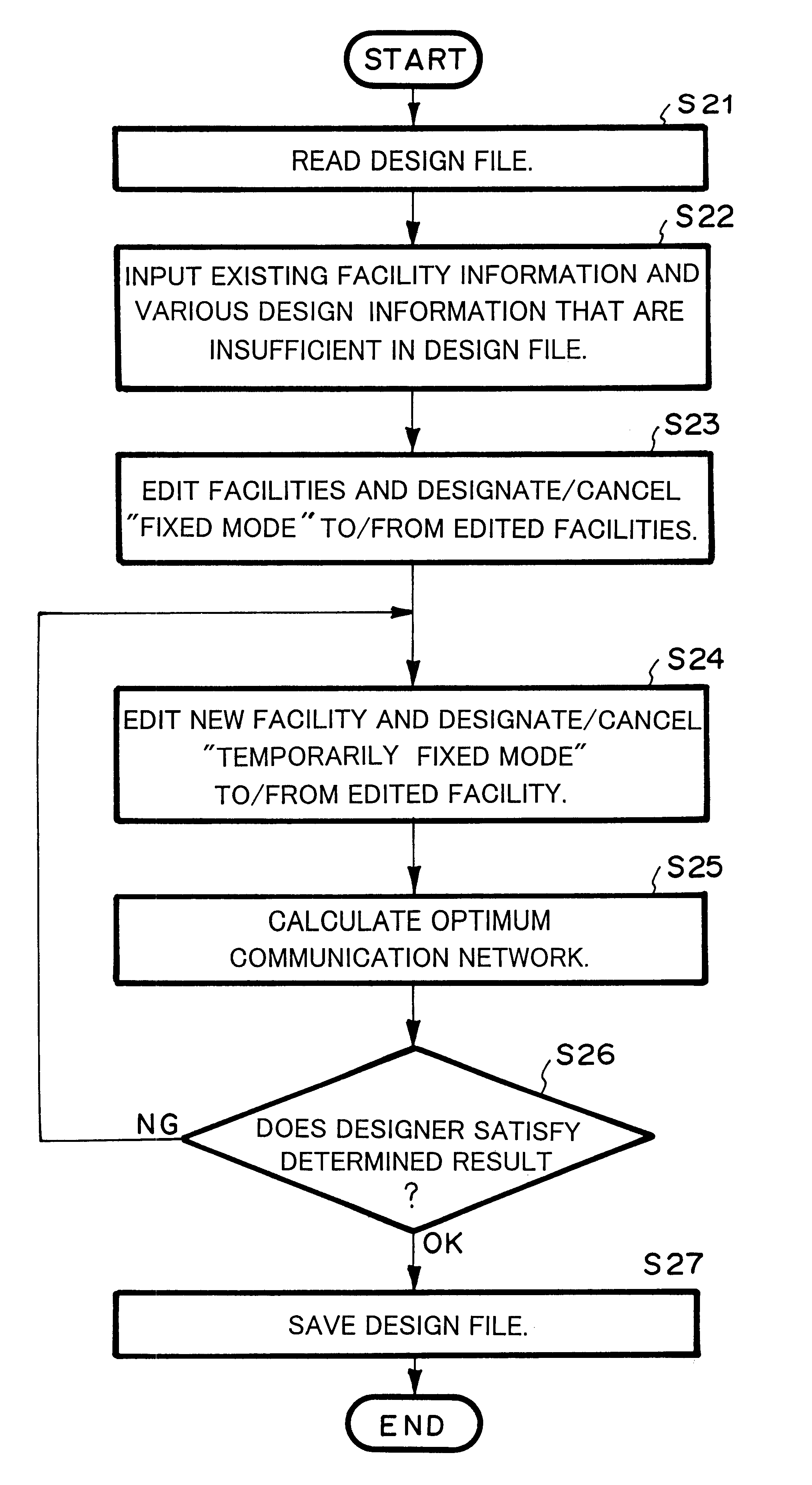
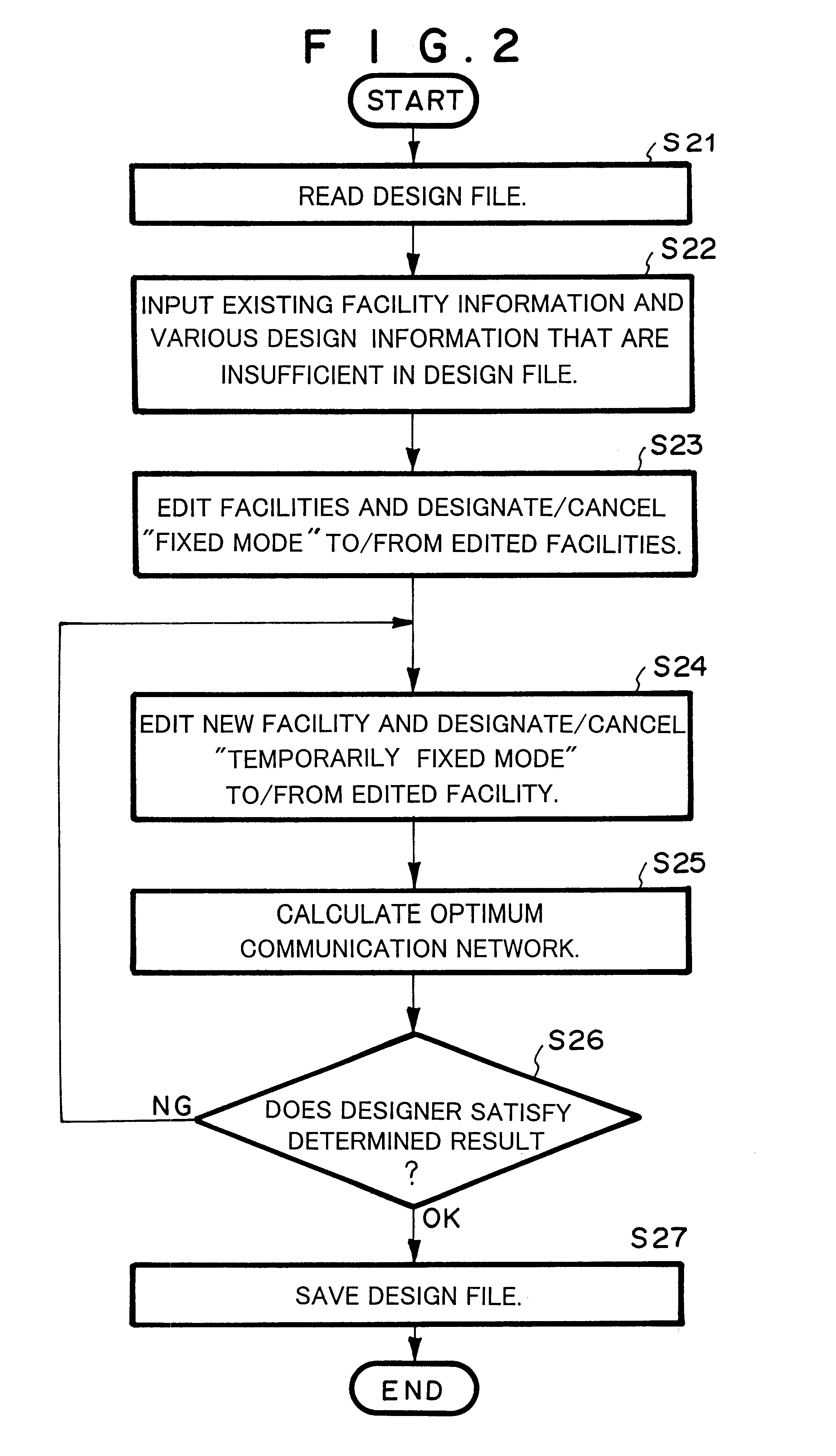
The designer inputs each item of input data 62 through a relevant module of the GUI portion 61. When the input data 62 is used in a communication network management system, communication facility data and cluster data can be directly imported as files. When each item of the input data 62 is input as data for an existing facility, the mode designating / canceling portion G7 designates the "fixed mode" to the cluster data S5, the communication facility data S9, and the civil construction facility data S10.

Each module of the optimized automatic designing portion 63 is executed in the direction of an arrow mark that represents the time axis. When each module of the optimized automatic designing portion ...


PUM


Abstract

The present invention is a designing method for designing an access communication network with a computer, the method including the steps of (a) reading a design file and inputting an existing facility information and a various parameter information, (b) designating and/or canceling a fixed mode to and from the existing facility information, (c) editing and inputting a temporarily fixed mode to an additional facility that has not been designed the fixed mode, (d) assigning a demand to facilities that have been designated the fixed mode or the temporarily fixed mode and calculating the structure of the access communication network and the positions of facilities thereof at low deployment costs that satisfy limited conditions of the various parameter information that has been input at the step (a), and (e) storing the structure of the calculated access communication network and the positions of facilities thereof to the design file.

Description

1. Field of the InventionThe present invention relates to a computer assisted access communication network designing system, a designing tool thereof, and a record medium from which a computer reads a program that causes the computer to accomplish the access communication network designing system. In particular, the present invention relates to a computer assisted access communication network system that calculates an access communication network structure and necessary civil construction facilities that are accomplished at low deployment costs and that satisfy a demand considering geographical shape, facility deployment position alternative, subscription demand, and existing facilities with limited conditions of communication quality, deployed positions of communication facilities, and so forth and relates to a designing tool thereof and a record medium from which a computer reads a program that causes the computer to accomplish the access communication network system.2. Descriptio...

Claims


Application Information

Patent Timeline
IPC IPC(8): G06F17/50H04L12/24H04M3/00
CPCG06F17/509H04L12/24H04L41/00G06F30/18
Inventor KAWAKAMI, HIROYUKIOKAZAKI, HIROYUKI
Owner NEC CORP
Why Eureka
Try Eureka