Profile

Inactive Publication Date: 2002-07-16
DEUTSCHES ZENTRUM FUER LUFT & RAUMFAHRT EV
View PDF9 Cites 68 Cited by
  • Summary
  • Abstract
  • Description
  • Claims
  • Application Information

AI Technical Summary

Benefits of technology

Preferably, a profile variation in the form of a change of curvature in the front profile region of the rotor blade is provided by lowering the nose. When active contour deformation is used in the nose region of a helicopter rotor blade profile, the appearance and effects of dynamic airflow break-away at the retreating rotor blade are advantageously reduced. Through the construction of a thin-walled profile according to the invention, in the form of a rotor blade, the dynamic airflow break-away can advantageously be shifted to larger angles of incidence, thus avoiding the otherwise inevitable loss of lift, reducing strong, pulse-like moment loading of the rotor blade, increasing the maximum speed of forward flight, optimizing the dynamic action of the rotor blade and affecting the aerodynamic center position and thus also the aeroelastic coupling.
An interesting embodiment may be obtained, for example, if the changes of contour in the region of the trailing edge of the profile are made in such a way that the upper surface of the profile remains unchanged while the lower surface of the profile is inwardly deformed, so that an S-shaped profile (S-shaped mean line) and / or a particular aerodynamic center stability (minimized variation of aerodynamic center position) is obtained. The combined change of arching and thickness, made possible by the local anisotropisms, have a particularly advantageous effect here.

Problems solved by technology

But constantly changing loads, caused by unsteady and non-homogeneous flows and causing unsteady lift and resistance forces, also have to be considered.
Where blades of helicopter rotors are used there is an unsteady airflow onto them.
As the speed of flight increases so too does the complexity of the flow conditions.
The break-away causes a sudden collapse in the lift, giving rise to a temporary, very strong moment load which turns the rotor blade top-heavily around the rotor's axis of rotation and produce s a structural-mechanical load.

Method used


Image

  • Profile
  • Profile
  • Profile

Examples


Embodiment Construction

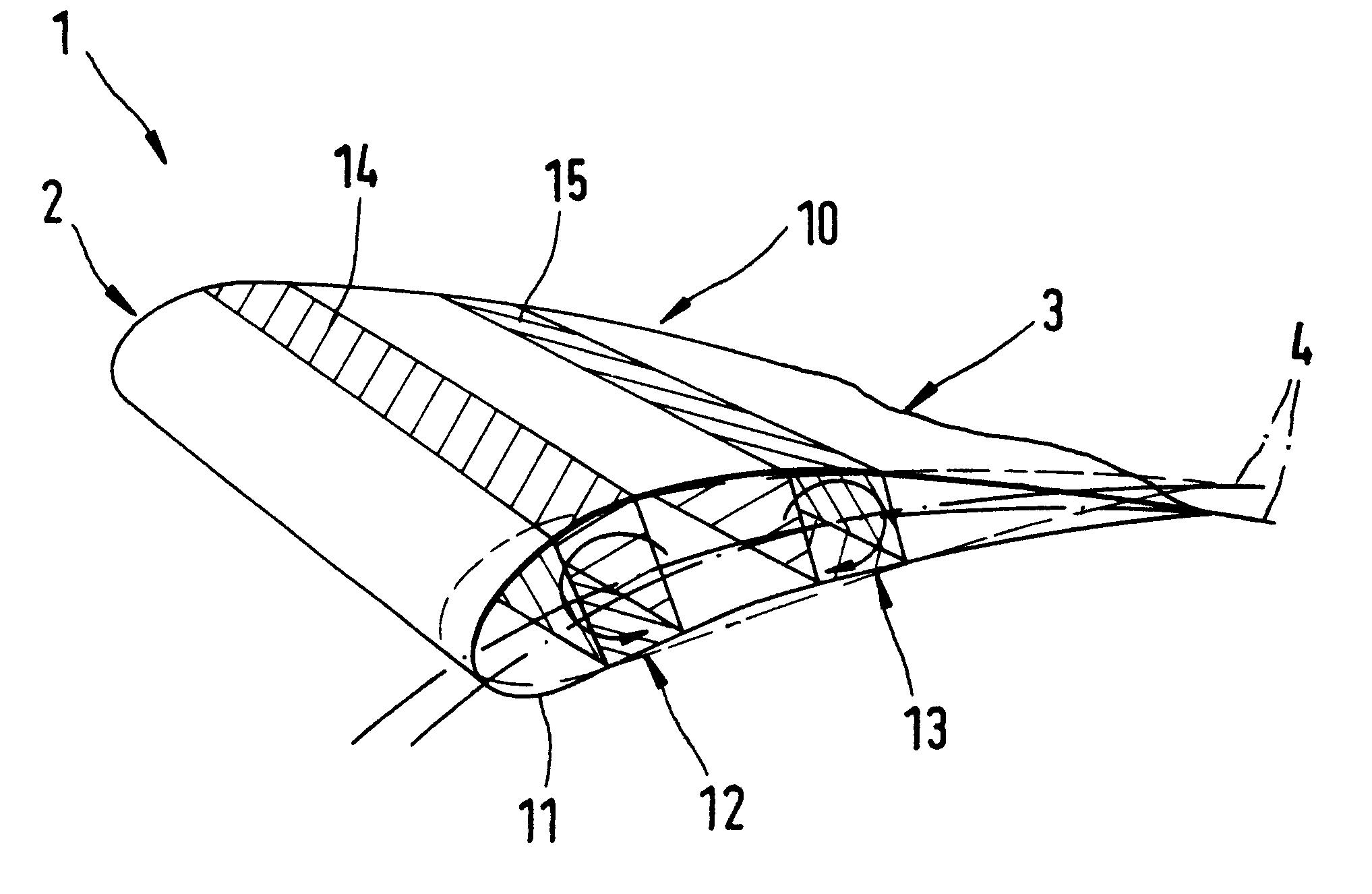
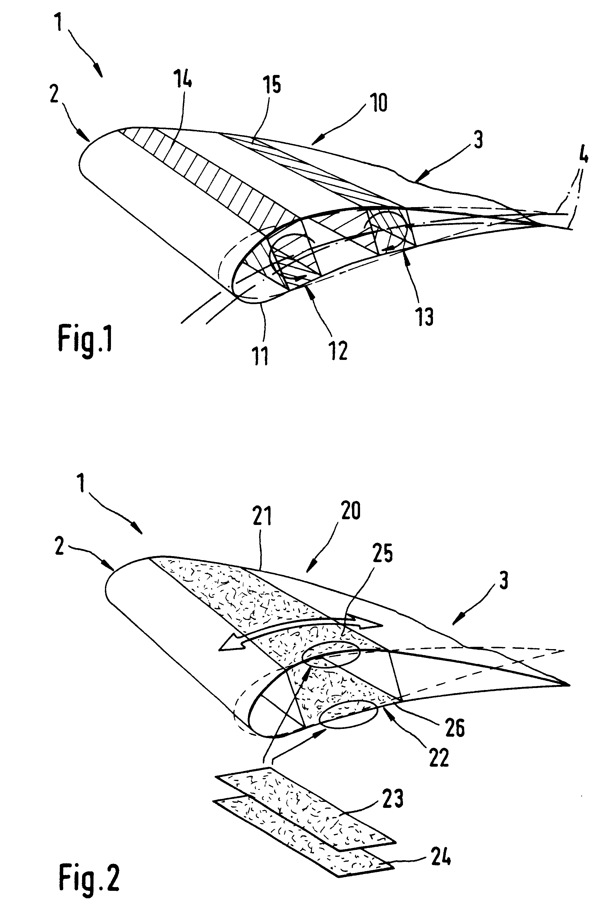
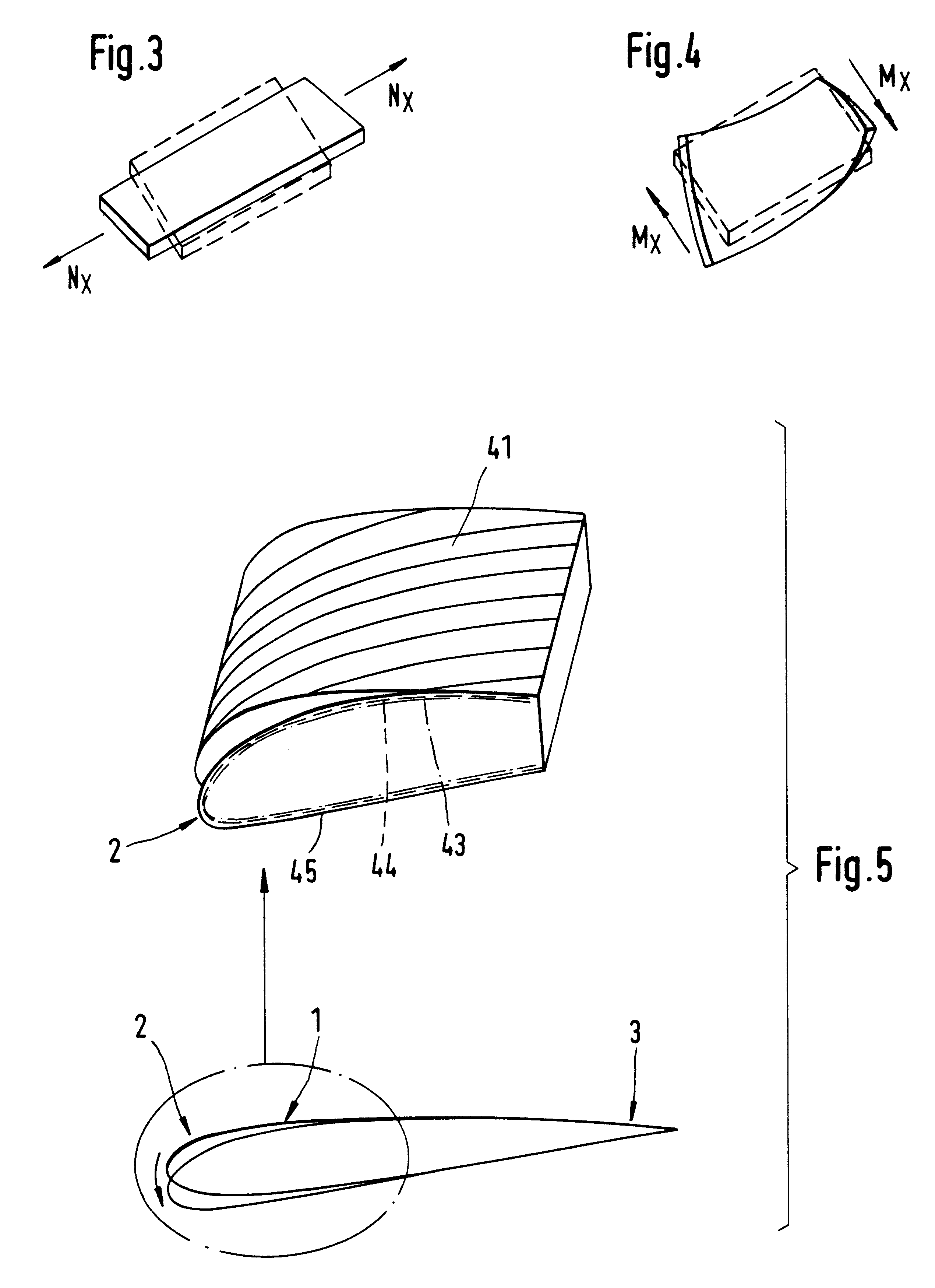
The present invention is directed to a thin-walled profile with material or structural anisotropisms provided locally in the profile to allow the contour of the profile to deform in a predetermined manner. "Anisotropism," as used herein, is used in the conventional sense, meaning a region that has physical properties that are different in different directions, allowing the region to assume different positions in response to external stimuli, such as an external force. The material or structural anisotropism may be, for example, a particular arrangement of material layers in a region of the of the profile. The anisotropisms cause deformation couplings which are used solely at individual components of the profile to deform the shape of the profile cross-section specifically and actively. The profile may, for example, be a single or multiple-cell, particularly thin-walled bar shell with the anisotropisms provided locally at its individual plate strips.

The thin-walled profiles of the pr...


PUM


Abstract

In a thin-walled profile with profile variation using anisotropisms due to the material or the structure, the anisotropisms due to the material or the structure are arranged locally in the profile to produce specific changes in the contour.

Description

1.0 Technical FieldThe invention relates to a profile member and, in particular, to a thin-walled profile member having localized material or structural anisotropisms.2.0 Background of Related ArtIt is known to use material or structural anisotropisms to produce global deformation couplings, for example, deformation couplings involving the whole cross-section of a profile, such as the tension-torsion or bending-torsion coupling.Aerodynamically effective contours, such as wings, rotor blades, propeller blades, compressor and turbine blades or other means are constantly being aerodynamically optimized. But constantly changing loads, caused by unsteady and non-homogeneous flows and causing unsteady lift and resistance forces, also have to be considered. Flaps or slats may be used to control these forces in a known manner.Where blades of helicopter rotors are used there is an unsteady airflow onto them. As the speed of flight increases so too does the complexity of the flow conditions. ...

Claims


Application Information

Patent Timeline
IPC IPC(8): B64C3/44B64C3/00
CPCB64C3/44Y02T50/145Y02T50/10
Inventor BUTER, ANDREASBREITBACH, ELMAREHLERT, ULF-CARSTEN
Owner DEUTSCHES ZENTRUM FUER LUFT & RAUMFAHRT EV
Why Eureka
Try Eureka