Efficient system and method for detecting and correcting laser misalignment of plural laser beams

a laser beam and laser misalignment technology, applied in the field of lasers, can solve problems such as degrade display quality, degrade image quality, and degrade image quality

Inactive Publication Date: 2002-07-23
SONY CORP
View PDF3 Cites 32 Cited by
  • Summary
  • Abstract
  • Description
  • Claims
  • Application Information

AI Technical Summary

Problems solved by technology

Undesirable laser beam deviation is particularly problematic in projection display applications, where beam misalignment may significantly degrade image quality.
In laser projection systems, optical components may shift over time, creating corresponding undesirable laser beam path deviations, which degrade display quality.
Misalignment of the coaxial beams relative to the desired optical axis degrades beam convergence on the screen, which degrades image quality.
Furthermore, beam misalignment may prevent proper illumination of light modul...

Method used


Image

  • Efficient system and method for detecting and correcting laser misalignment of plural laser beams
  • Efficient system and method for detecting and correcting laser misalignment of plural laser beams
  • Efficient system and method for detecting and correcting laser misalignment of plural laser beams

Examples


Embodiment Construction

While the present invention is described herein with reference to illustrative embodiments for particular applications, it should be understood that the invention is not limited thereto. Those having ordinary skill in the art and access to the teachings provided herein will recognize additional modifications, applications, and embodiments within the scope thereof and additional fields in which the present invention would be of significant utility.

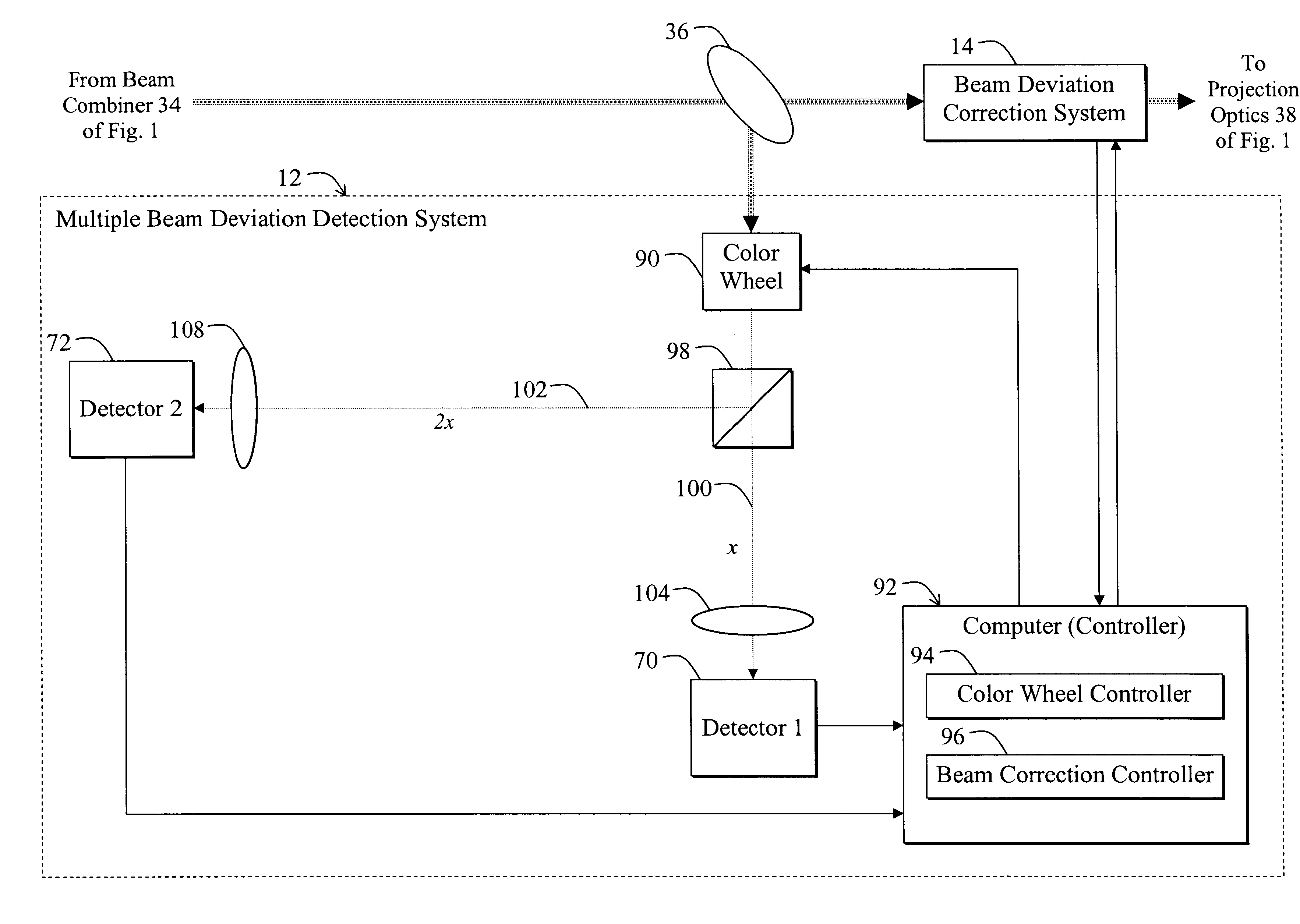
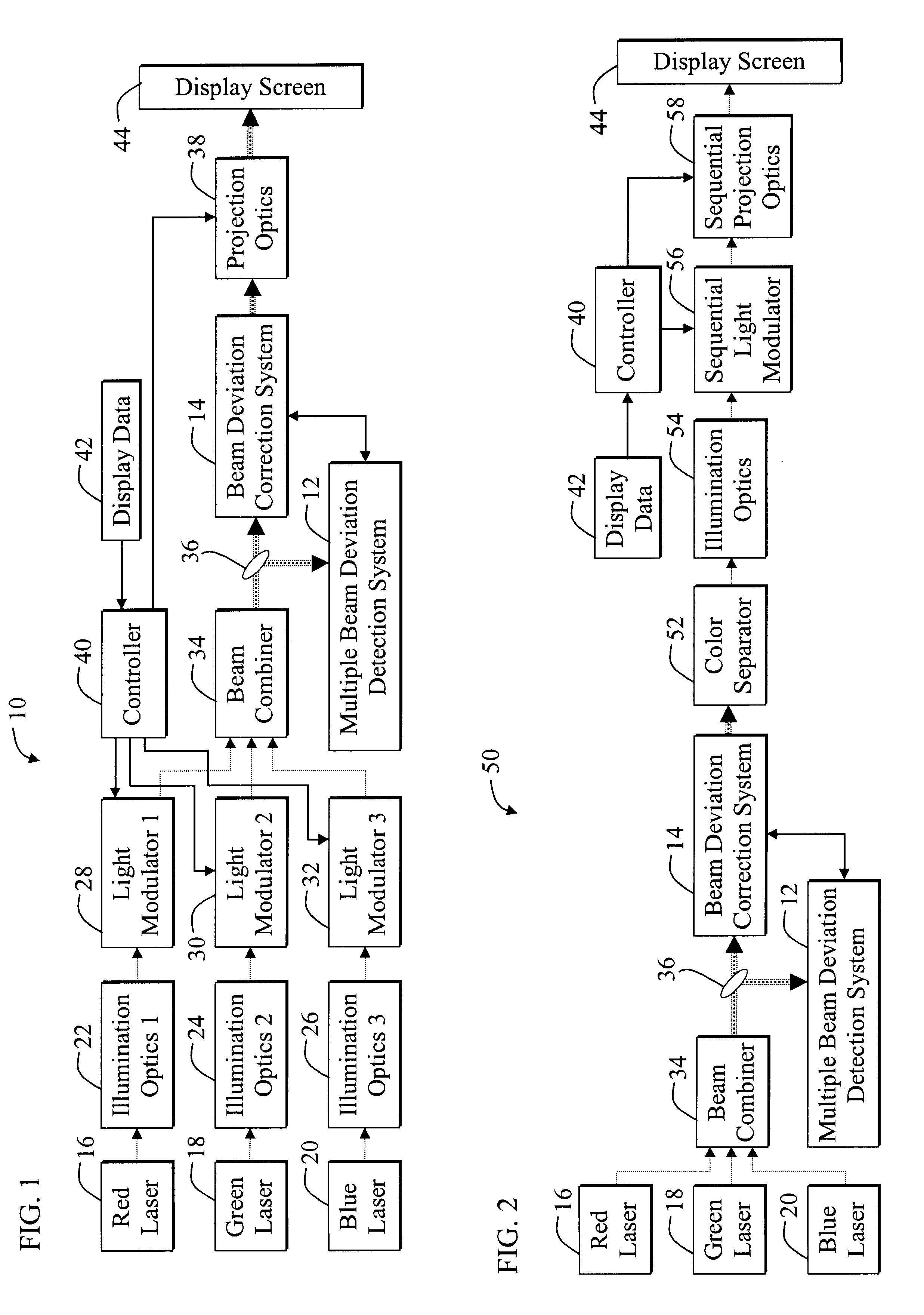
FIG. 1 is a diagram of a laser projection system 10 having a unique multiple beam deviation detection system 12 and deviation correction system 14 constructed in accordance with the teachings of the present invention. For clarity, various components, such as power sources and image input devices, are not shown in FIG. 1, however one skilled in the art with access to the present teachings will know where and how to implement the additional requisite components.

The laser projection system 10 includes a red laser 16, a green laser 18, and a bl...


PUM


Abstract

A system for detecting deviations from an optical axis of one or more individual component beams associated with plural laser beams. The system includes a first mechanism that selectively isolates individual component beams from plural laser beams and provides the individual component beams as output in response thereto. A second mechanism detects deviations from a desired optical axis of the individual component beams output from the first mechanism. In the specific embodiment, the system further includes a mechanism that automatically corrects the detected deviations of each component beam of the plural beams. A beam pick-off device, such as a pick-off collimating lens or beam splitter, redirects a sample of the plural beams, which represents separated plural beams to a color wheel. The individual component beams include red, green, and blue laser beams. The color wheel selectively isolates the red, green, and/or blue beams from the separated plural beams and provides an isolated component beam as output in response thereto. A beam splitter splits the isolated component beam into a first split beam and a second split beam and directs the first split beam and the second split beam along a first optical path that terminates at a first detector and a second optical path that terminates at a second detector, respectively. The lengths of the first and second optical paths differ by a predetermined distance. Software running on a computer compares the relative position of the first split beam on the first detector to the position of the second split beam on the second detector with reference to the predetermined distance and provides a beam deviation signal in response thereto. The software then actuates a beam deviation correction system to correct for beam deviations indicated by the beam deviation signal associated with the isolated beam in the plural beams.

Description

1. Field of InventionThis invention relates to lasers. Specifically, the present invention relates to systems and methods for detecting and correcting beam misalignment in systems employing multiple laser beams, such as projection display and other laser systems.2. Description of the Related ArtMultiple laser beams are employed in various demanding applications including front and rear projection devices in movie theaters, home theater systems, heads-up displays for automobiles and aircraft cockpits, and design workstations. Such applications often require precise coaxial alignment of multiple laser beams for maximum display quality. Typically, each beam of the multiple beams is at a different frequency.Undesirable laser beam deviation is particularly problematic in projection display applications, where beam misalignment may significantly degrade image quality. In laser projection systems, optical components may shift over time, creating corresponding undesirable laser beam path de...

Claims


Application Information

Patent Timeline
IPC IPC(8): G01B11/26G01B11/00G02B27/00G02B27/01G02B27/18H01S3/00H01S3/101
CPCG01B11/26G02B27/01G02B27/0101H04N9/3129H04N9/3164H04N9/3185G02B27/0031G02B2027/011H01S3/005H04N3/22
Inventor MATTHEWS, EDWARD W.
Owner SONY CORP
Why Eureka
Try Eureka