Pull element travel sensor

a technology of travel sensor and pulley, which is applied in the direction of mechanical measurement arrangement, instruments, using mechanical means, etc., can solve the problems of limited service life, high mechanical wear, and the peripheral length of a single winding on the winding drum becomes progressively greater

Inactive Publication Date: 2002-08-13
ASM AUTOMATION SENSORIK MESSTECHN GMBH
View PDF7 Cites 3 Cited by
  • Summary
  • Abstract
  • Description
  • Claims
  • Application Information

AI Technical Summary

Problems solved by technology

A disadvantage with that structure is that it is necessary to use a pull element of a special configuration whose differing portions must remain unchanged, even over a long period of time and even after a large number of operations of being wound on to and unwound from the winding drum.
In the case of portions of different configurations on the pull element, such as for example holes, tooth arrangements and the like, they tend to be subjected to a high level of mechanical wear and thus enjoy only a limited service life.
The disadvantage that this apparently entails in terms of evaluation of the length of the winding element which is drawn off or wound on to the winding drum, more specifically that with increasing winding of the pull element on the winding drum the peripheral length of a single winding on the winding drum becomes progressively greater, is eliminated by a non-mechanical electronic device.
As measurement sensors of that kind are intended to implement opera

Method used


Image

  • Pull element travel sensor
  • Pull element travel sensor
  • Pull element travel sensor

Examples


Embodiment Construction

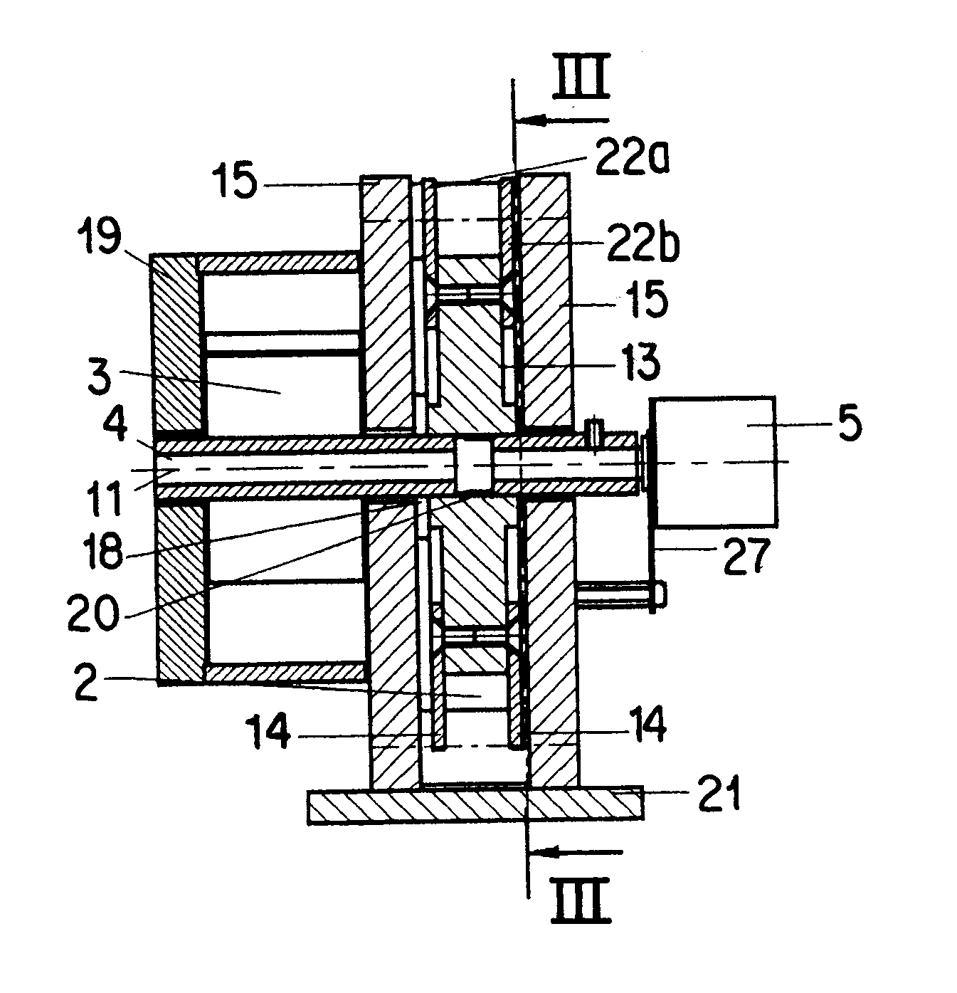
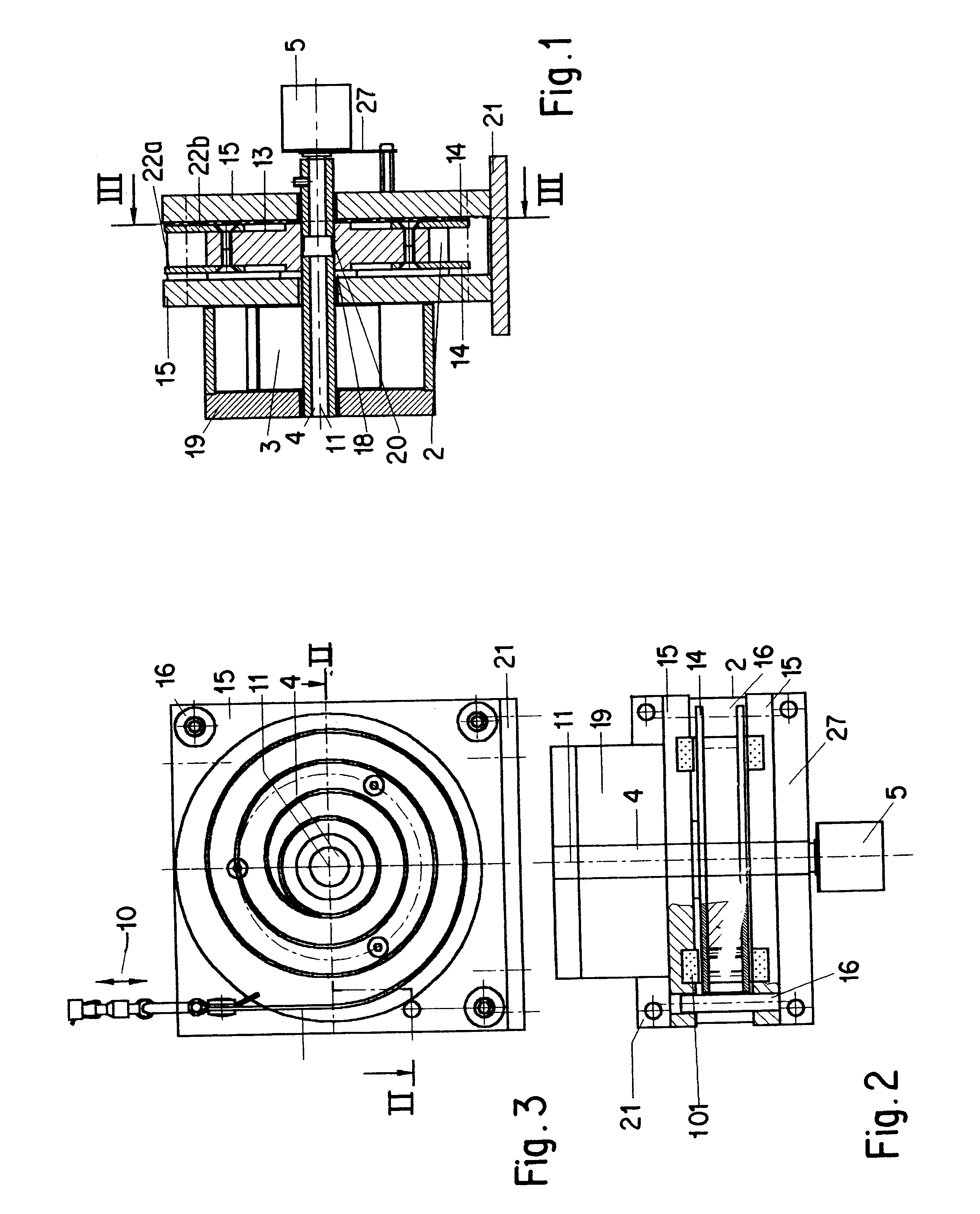
Referring firstly to FIGS. 1 through 3, it will be noted at this point that, while FIGS. 1 and 2 show the pull element travel sensor according to the invention, for reasons of clarity of the drawing, without the tensile or pull element which will generally be in the form of a band or belt, the band or belt forming the pull element is in fact shown in FIG. 3 and indicated therein by reference numeral 1, including spiral winding thereof on a measuring or winding drum generally identified by reference numeral 2 in FIGS. 1 through 3. The cross-sectional view in FIG. 1 shows the coaxial arrangement of the winding drum 2, a rotary angle sensor 5 for detecting the rotary movement or the angular positioning of the winding drum 2, and a flat spiral spring 3 operable to urge the winding drum 2 in the direction of winding the pull element or band 1 on to same.

As can be seen from FIG. 1, the winding drum 2 comprises a drum core 13 which is fixed non-rotatably by means of a tolerance ring 20 on ...


PUM


Abstract

A pull element travel sensor include a winding drum and a pull element which can be wound on to and unwound from the winding drum. The winding drum is biassed in the pull element winding-on direction. The length of the pull element which is pulled off the winding drum can be detected by a detecting unit. The pull element is wound on the winding drum in a spiral configuration in a plurality of layers in mutually superposed relationship in a single radial plane of the winding drum. A lifting apparatus for lifting a load has at least two lifting units and at least one travel sensor, each lifting unit having a winding drum with a pull element and a motor for driving the winding drum in the winding-on direction. At least one of the lifting units has a detecting unit for detecting the drawn-off length of the pull element from the winding drum, with all pull elements of the lifting units engaging the same load.

Description

1. Field of the InventionThe invention concerns a pull element travel sensor and a lifting apparatus embodied with such elements.2. Background of the InventionPull element travel sensors occur in many different configurations for example in order to determine the precise positioning of a given component which in particular can move over considerable travel distances, for example the cabin of an elevator. A typical pull element travel sensor of that kind has a tensile or pull element, for example a cable, which is wound on to a winding drum which is biassed in the winding-on direction. The free end of the pull element is connected to that component whose position is to be determined, for example as mentioned above an elevator cabin. A prestressing force for urging the winding drum in the winding-on direction is produced for example by way of a flat spiral spring which for example is arranged coaxially with respect to the winding drum and is non-rotatably connected thereto.The winding...

Claims


Application Information

Patent Timeline
IPC IPC(8): G01B7/02G01B3/11
CPCG01B3/11G01B7/026
Inventor STEINICH, KLAUS-MANFRED
Owner ASM AUTOMATION SENSORIK MESSTECHN GMBH
Why Eureka
Try Eureka