In contrast to the prior art, the present invention accordingly displaces the coupling element for canceling the
rotational coupling of the converter housing and turbine wheel, i.e., for disengaging the lockup clutch against the pressure of the converter work fluid prevailing in the interior space of the converter housing, by filling the pressure fluid space with pressure fluid. This results in some substantial advantages with respect to operation which have a positive effect on the efficiency of the converter operation in particular. First, the pressure fluid space need only be filled with pressure fluid when the lockup clutch is to be partially or fully disengaged. However, this operating state occurs only relatively briefly during normal driving, for example when starting or shifting gears. During normal driving, the converter does not perform its converter function, but rather is bypassed by the engagement of the lockup clutch. Therefore, the time period during which a pump must be put into operation for filling the pressure fluid space with pressure fluid is clearly reduced. Further, the pressure of the converter work fluid prevailing in the interior space of the converter housing in the engaged state of the lockup clutch acts upon the coupling element due to the reduction of
fluid pressure in the pressure fluid space and presses the coupling element for engaging the lockup clutch. Consequently, it is not necessary to work against the pressure of the converter work fluid prevailing in the interior space of the converter housing for engaging the lockup clutch; rather, this pressure can be utilized in a positive fashion to produce the lockup state. This means that the
fluid pressure in the interior space of the converter housing can be held at a normal or high level also in the lockup state, so that spontaneous transitions in converter operation also do not lead to
cavitation problems or loss of output.
Also, the efficiency of an entire torque converter
system, especially also in the region of the lockup clutch, can be increased by such an arrangement. This arrangement ensures that the circuit of the converter work fluid, i.e., the supply of converter work fluid and the
discharge of converter work fluid, can be directed in a defined manner via the area of a friction lining arrangement, so that defined cooling conditions can be adjusted in this case without having to utilize the supply of fluid to the pressure fluid space for this purpose as is the case, for instance, with torque
converters with an open three-line
system.
In a construction of this type, it can preferably be provided that the pressure fluid space does not communicate so as to exchange converter
working fluid with the interior space of the converter housing. Further, it is advantageous when the pressure fluid space can be filled with pressure fluid for the displacement of the coupling element for at least partial cancellation of the rotational coupling of the converter housing and turbine wheel.
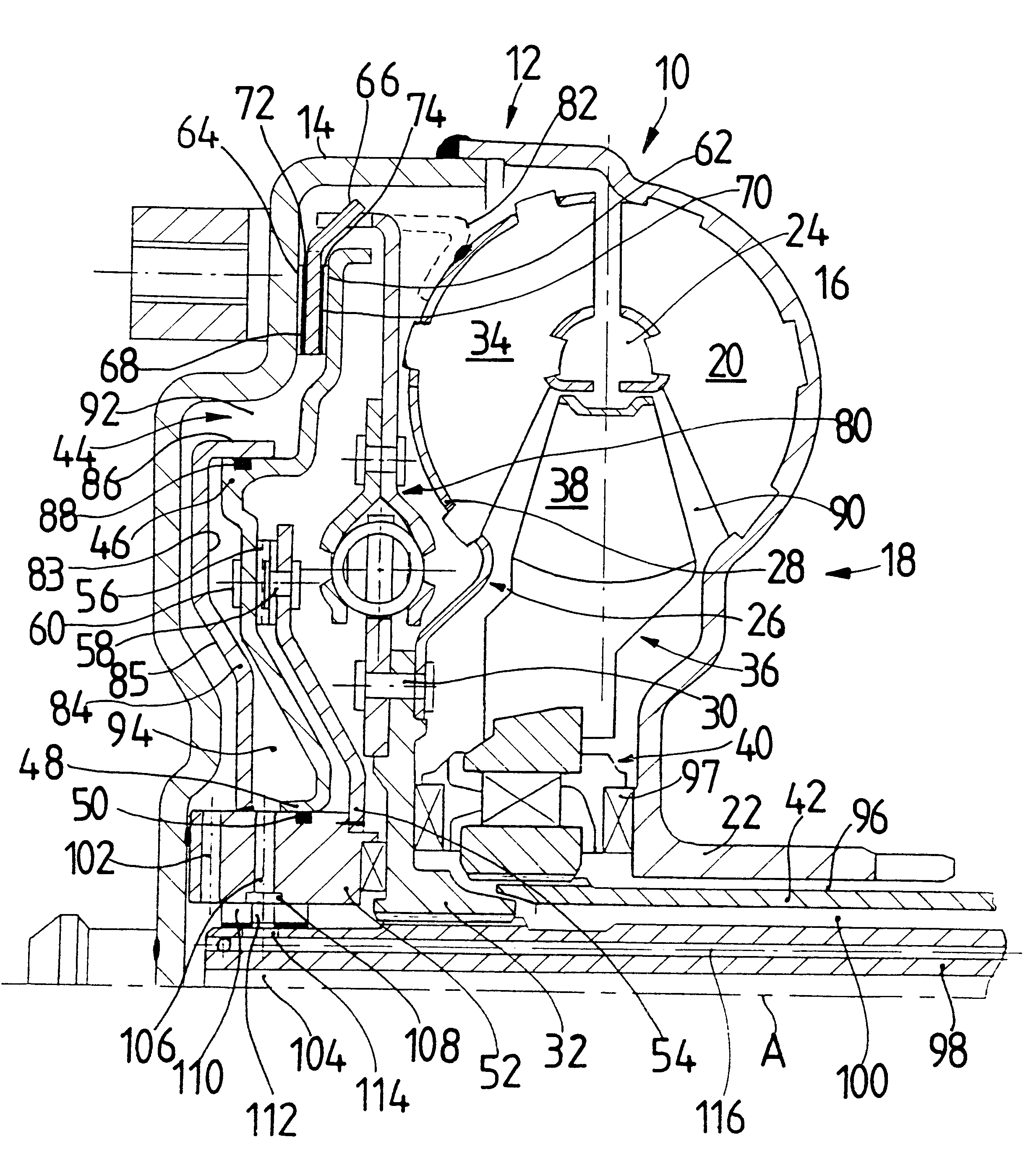
According to another aspect of the present invention, a pressure fluid space housing can be provided in a hydrodynamic torque converter, this pressure fluid space housing at least partially defining the pressure fluid space at a first side and defining one of the converter work fluid spaces at least in some areas at a second side. In this way, a simple spatial division into one of the converter work fluid spaces on the one hand and of the pressure fluid space on the other hand can be achieved. In this respect, it is preferably provided that the pressure fluid space housing is arranged between the coupling element and the converter housing, wherein the pressure fluid space housing, together with the coupling element, defines the pressure fluid space at least in some areas and, together with the converter housing, defines the one converter work fluid space at least in some areas.
In a further embodiment of the present invention, the pressure fluid space housing is connected with the converter housing so as to be substantially fixed with respect to rotation relative to it. This leads to the
advantage that the torque converter can be constructed in a simple manner in such a way that the lockup clutch has at least one friction
surface element which is connected with the turbine wheel so as to be essentially fixed with respect to rotation relative to it and which can be clamped between the converter housing and the coupling element for producing the rotational coupling of the turbine wheel and converter housing. In this case, a relatively large quantity of friction surfaces and a correspondingly strong rotational coupling can be produced between the converter housing and turbine wheel.

