Sliding roof device

a technology of sliding roof and sunroof, which is applied in the direction of roofs, mechanical equipment, transportation and packaging, etc., can solve the problems of increasing the number of parts heavy weight of sliding roof devices, and cumbersome securing

Inactive Publication Date: 2002-08-13
AISIN SEIKI KK
View PDF19 Cites 45 Cited by
  • Summary
  • Abstract
  • Description
  • Claims
  • Application Information

AI Technical Summary

Problems solved by technology

The box is formed of a metal due to the fact the box has to have a sufficient mechanical strength, which results in that the sliding roof device becomes heavy in weight.
Also, the box is in the form of a separation member relative to the frame, which leads to an increase of the number of parts of the sliding roof device.
Moreover, in the foregoing structure, after connecting the casing pipe to the box, the resulting box is secured to the frame, with the results that such a securing is very cumbersome.
However, the aforementioned securing of the casing ...

Method used


Image

  • Sliding roof device
  • Sliding roof device
  • Sliding roof device

Examples


Embodiment Construction

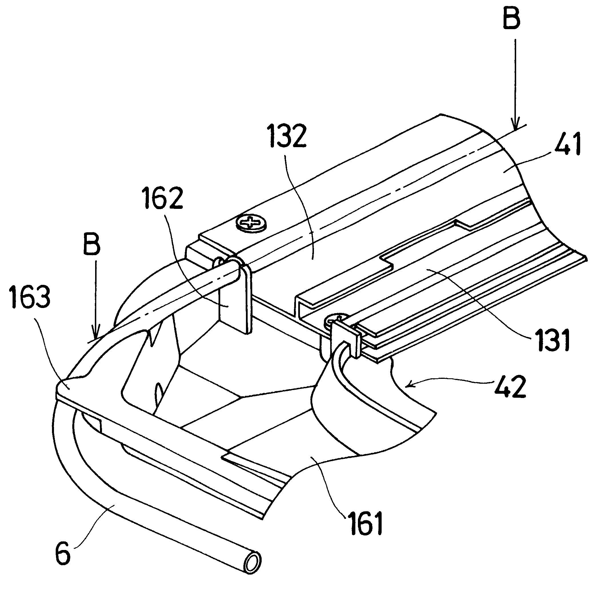
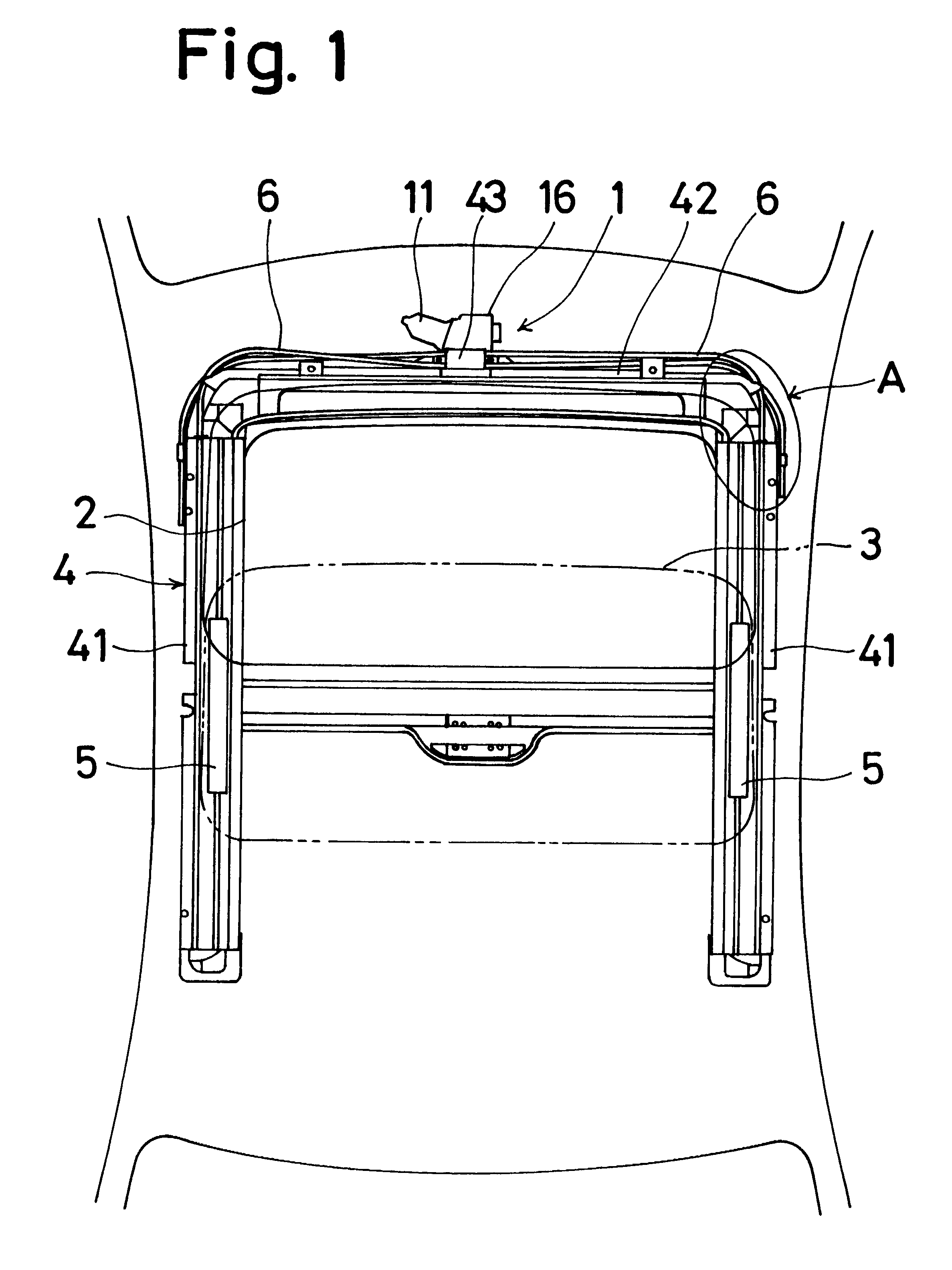
First of all, with reference to FIG. 1, which illustrates a top view of a sun roof or sliding roof, which employs a driving device or mechanism 1, a vehicular roof panel is formed therein with an open portion or area 2. A pair of guide rails 41 and 41 extend in a vehicular longitudinal direction in FIG. 1 along a pair of opposed inner peripheries of the open portion 2, respectively and are secured thereto. A movable or slide panel 3 is supported by the guide rails 41 and 41 so as to be movable or slidable in the vehicular longitudinal direction. At a front periphery of the open portion 2, there is provided a resin-made front frame 42 to which a front end of each of the guide rails 41 and 41 is connected in the vertical direction. The pair of the guide rails 41 and 41 and the front frame 42 constitute a sunroof frame 4.

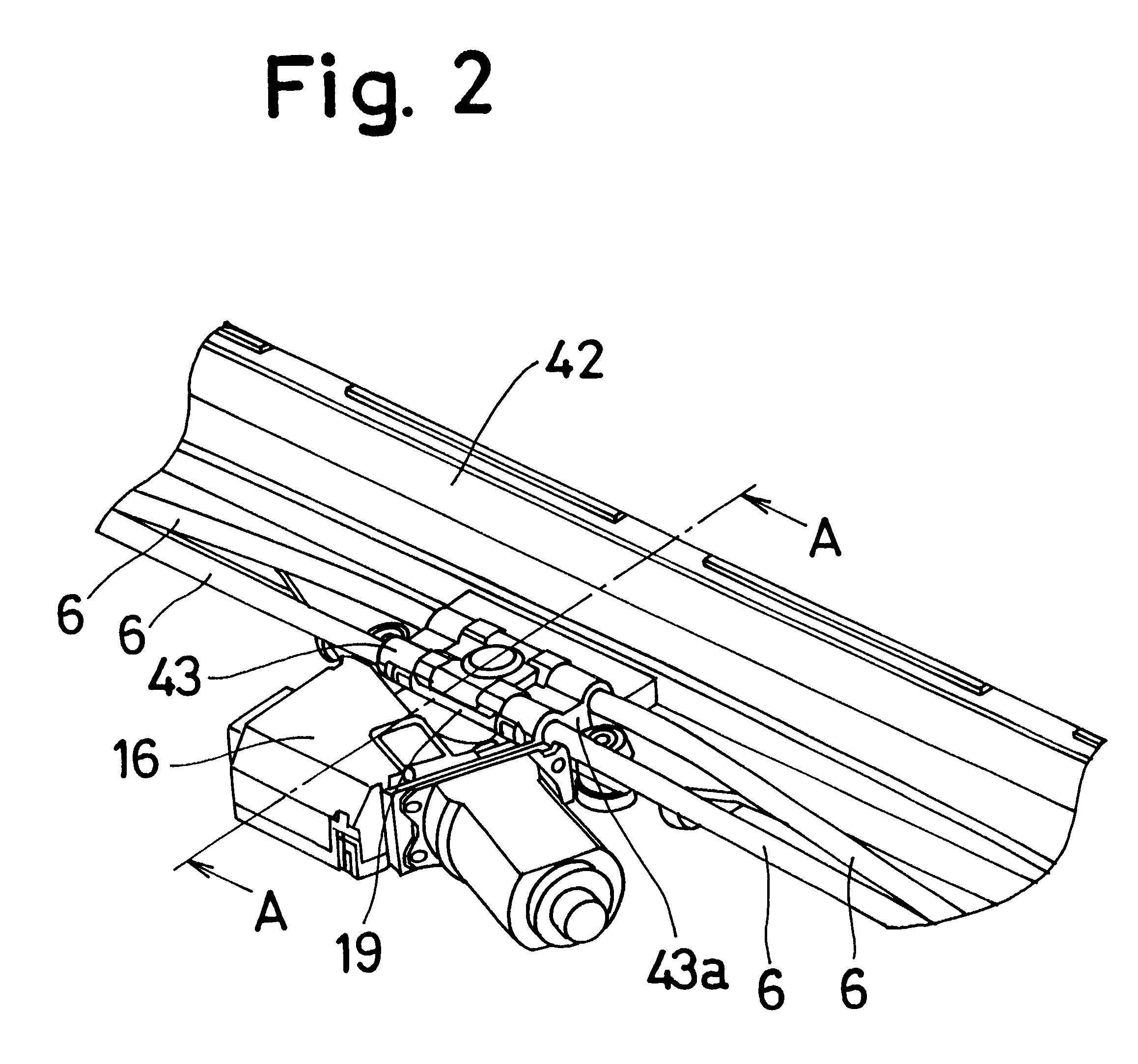
At the front frame 42 positioned at the front periphery of the open area 2, the driving mechanism 1 drives the slide panel 3 to open and close the open area 2 in such ...


PUM


Abstract

A sliding roof device is made up of a pair of laterally spaced guide rails provided at inner peripheries of an open area formed in a vehicular roof panel, the guide rails supporting a movable panel in movable fashion in order to open and close the open area; a front frame connecting a front end of one of the guide rails and a front end of the other, the front frame and the pair of the guide rails constituting a sunroof frame; and a driving mechanism including a motor, a gear mechanism driven by the motor, an output gear associated with the gear mechanism, a geared cable engaged with the output gear in meshing fashion and connected to the movable panel for the movement thereof when the motor is turned on, and a casing pipe through which the geared cable is passed in movable fashion, characterized in that a housing and a box are provided, the housing placing the output gear outside the sunroof frame, the housing accommodating therein the gear mechanism, the box being formed integrally with the sunroof frame, the box covering the meshing engagement between the geared cable and the output gear.

Description

1. Field of the InventionThe present invention is directed to a vehicular sliding roof or sunroof device.2. Prior ArtIn general, typical conventional or prior art sliding roof devices are made up of(a) a pair of laterally spaced guide rails provided at inner peripheries of an open area formed in a vehicular roof panel, the guide rails supporting a movable panel in movable fashion in order to open and closes the open area;(b) a front frame connecting a front end of one of the guide rails and a front end of the other, the front frame and the pair of the guide rails constituting a sunroof frame; and(c) a driving mechanism including a motor, a gear mechanism driven by the motor, an output gear associated with the gear mechanism, a geared cable engaged with the output gear in meshing fashion and connected to the movable panel for the movement thereof when the motor is turned on, and a casing pipe through which the geared cable is passed in movable fashion.For example, in Japanese Unexami...

Claims


Application Information

Patent Timeline
IPC IPC(8): B60J7/057B60J7/02B60J7/04
CPCB60J7/022B60J7/057B60J7/0573
Inventor NAGASHIMA, YOUJIMAETA, KENJIMAKINO, HIROSHIKITANI, TAKASHI
Owner AISIN SEIKI KK
Why Eureka
Try Eureka