Mechanical timepiece with timed annular balance rotating angle control mechanism

a control mechanism and mechanical technology, applied in the direction of electric winding, instruments, horology, etc., can solve the problems of -3 seconds per day delay and slow down of instantaneous watch error

Inactive Publication Date: 2002-08-13
SEIKO INSTR INC
View PDF8 Cites 12 Cited by
  • Summary
  • Abstract
  • Description
  • Claims
  • Application Information

AI Technical Summary

Benefits of technology

to provide a mechanical timepiece having a balance-with-hairspring rotation angle control mechanism

Problems solved by technology

In the case of FIG. 10, the instantaneous watch error delays when the swing angle of the balance with hairspring is 240 degrees or greater or 200 degrees or smaller.
Generally, in the conventional mechanical timepiece, the instantaneous watch error slows down because the mainspring torque decreases

Method used


Image

  • Mechanical timepiece with timed annular balance rotating angle control mechanism
  • Mechanical timepiece with timed annular balance rotating angle control mechanism
  • Mechanical timepiece with timed annular balance rotating angle control mechanism

Examples


Embodiment Construction

Hereunder, embodiments of a mechanical timepiece of the present invention will be explained based on the drawings.

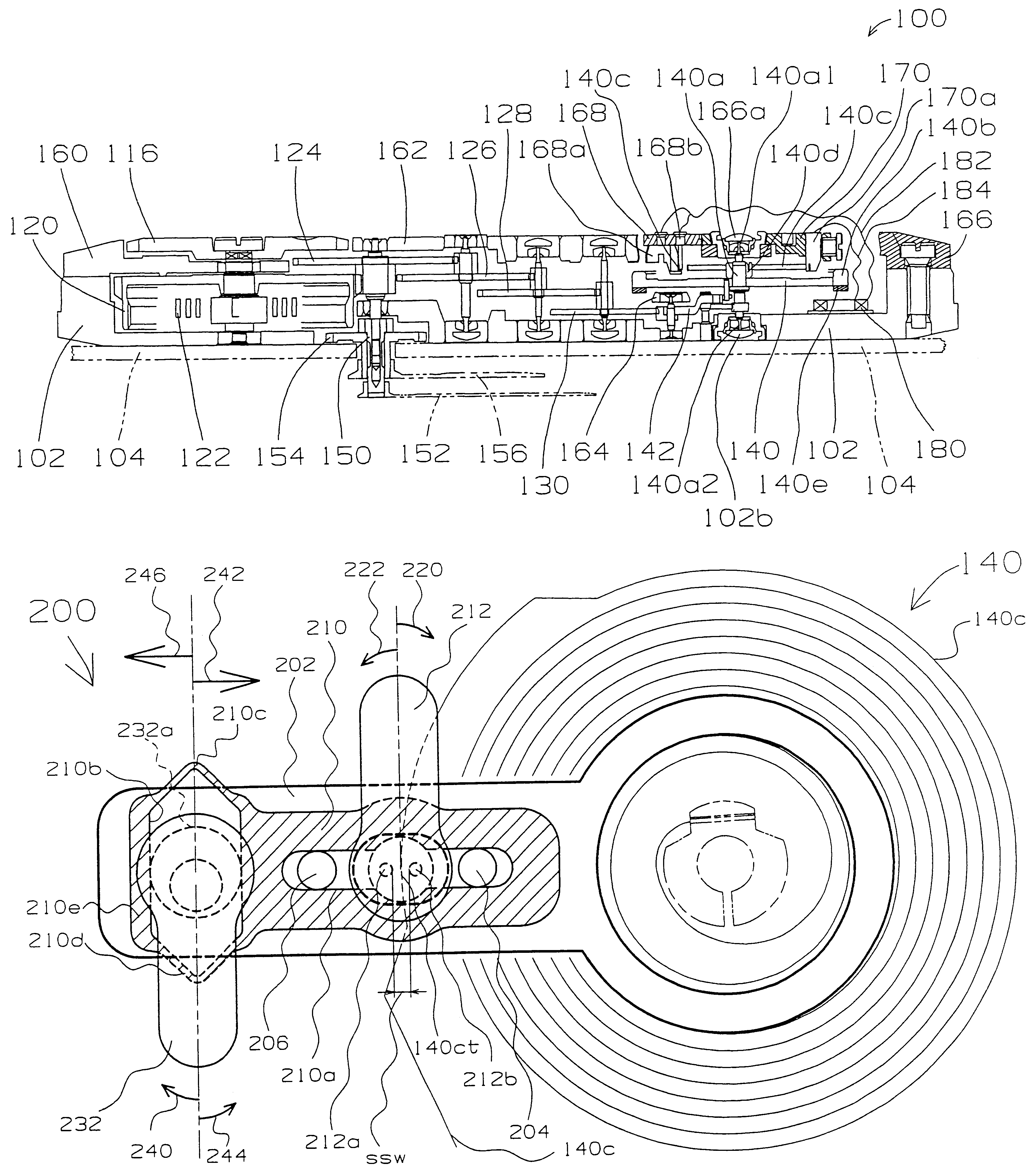
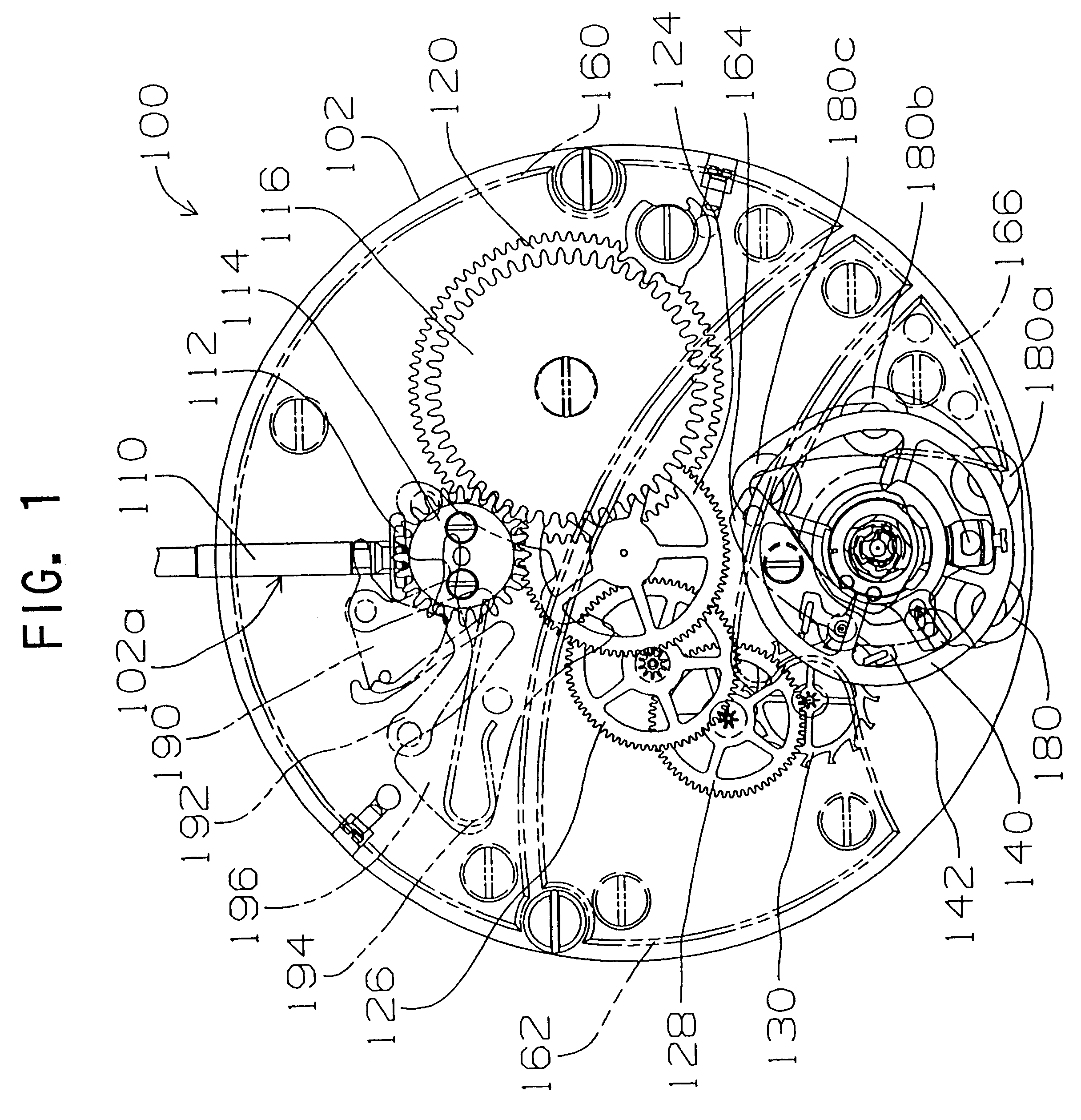
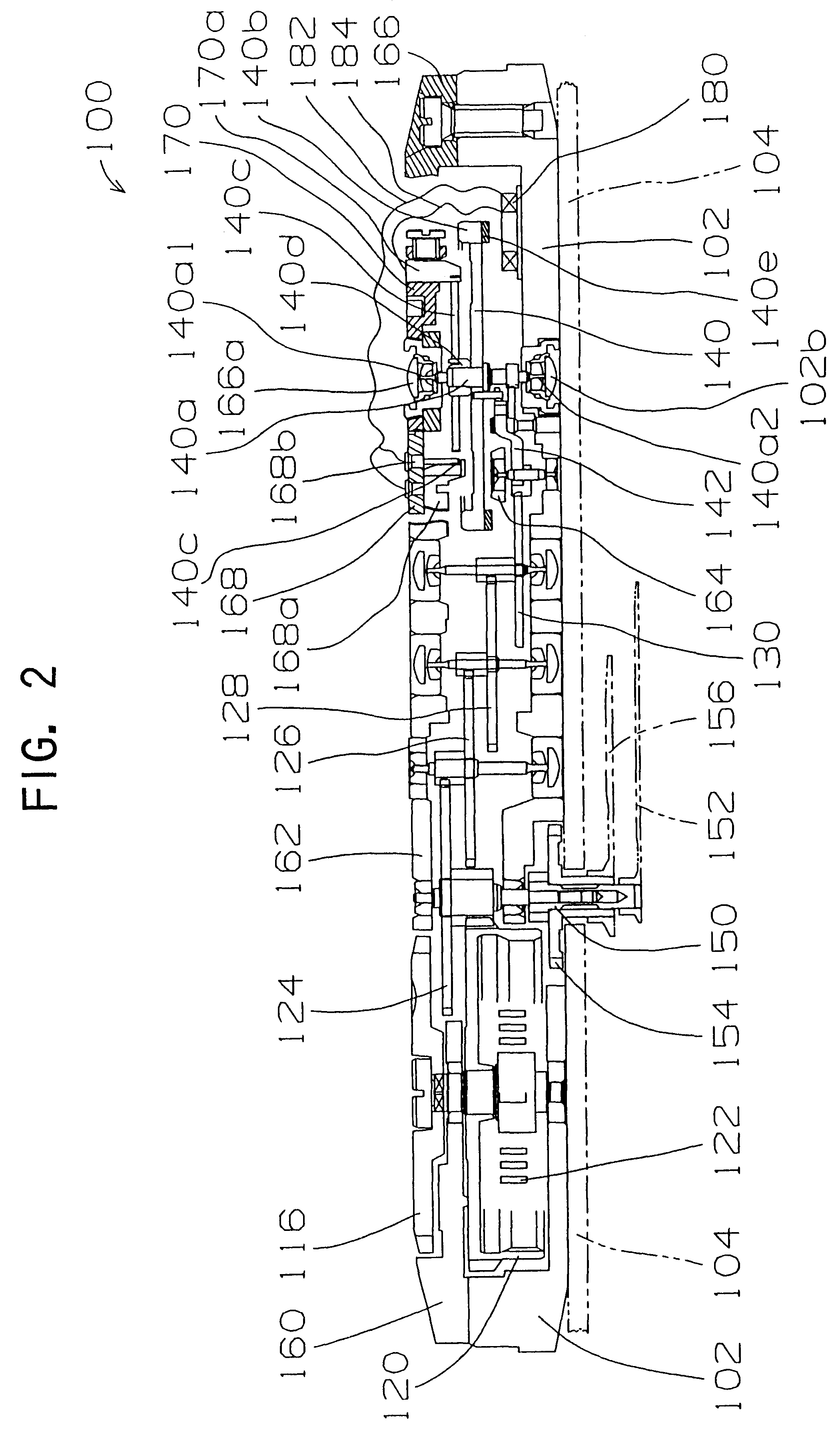
Referring to FIG. 1 and FIG. 2, in an embodiment of a mechanical timepiece of the invention, a movement (mechanical body) 100 of the mechanical timepiece has a main plate 102 structuring a base plate for the movement. A hand setting stem 110 is rotatably assembled in a winding-stem guide hole 102a of the main plate 102. A dial 104 (shown by a virtual line in FIG. 2) is attached on the movement 100.

The hand setting stem 110 has a squared portion and a guide shaft portion. A clutch wheel (not shown) is assembled on the square portion of the hand setting stem 110. The clutch wheel has a same rotation axis as a rotation axis of the hand setting stem 110. That is, the clutch wheel is provided having a squared hole and rotated based on rotation of the hand setting stem 110 by fitting the squared hole on the squared portion of the hand setting stem 110. The clutch wheel has tee...


PUM


Abstract

A mechanical timepiece has a power source comprised of a mainspring for undergoing rewinding movement to generate a rotational force. A front train wheel undergoes rotation in accordance with a rotational force generated during rewinding movement of the mainspring. An escapement/speed-control device controls rotation of the front train wheel. The escapement/speed-control device has a balance with a hairspring for undergoing alternately repeating rotational movement in left and right directions. An escape wheel and pinion undergoes rotation in accordance with rotation of the front train wheel. A pallet fork controls rotation of the escape wheel and pinion in accordance with rotational movement of the balance. A switch mechanism outputs an ON signal when a rotation angle of the balance reaches a predetermined threshold angle or greater, outputs an OFF signal when the rotation angle of the balance does not exceed the predetermined threshold angle. A rotation angle control mechanism supresses rotation of the balance when the switch mechanism outputs an ON signal.

Description

Field of the InventionThe present invention relates to a mechanical timepiece having a mechanical timepiece having a balance-with-hairspring rotation angle control mechanism structured to apply to the balance with hairspring such a force as suppressing against rotation of the balance with hairspring. Also, the invention relates to a mechanical timepiece having a switch adjuster mechanism used to adjust positions of a first contact member and second contact member relative to a near-outer-end portion of the stud-mainspring and a spacing between the first contact member and the second contact member. Furthermore, the invention relates to a mechanical-timepiece adjuster device for adjusting positions of first contact and second contact members relative to a near-outer-portion of the stud mainspring.Background InformationIn the conventional mechanical timepiece, as shown in FIG. 13 and FIG. 14 the mechanical-timepiece movement 1100 (mechanical body) has a main plate 1102 constituting a ...

Claims


Application Information

Patent Timeline
IPC IPC(8): G04B17/06G04B17/00G04C3/00G04C3/06G04C10/00G04C11/08
CPCG04C10/00G04C11/084
Inventor JUJO, KOICHIROTOKORO, TAKESHI
Owner SEIKO INSTR INC
Why Eureka
Try Eureka