Striker bar for disintegrating breakable materials

a technology of breakable materials and striker bars, which is applied in the field of striker bars, can solve the problems of large amount of dust and small particles produced, cutting edges, and prone to wear at a relatively rapid rate, and achieve the effects of reducing the amount of dust and small particles generated during operation, reducing energy consumption, and increasing the throughput rate of materials

Inactive Publication Date: 2002-08-20
SANDVIK ROCK TOOLS
View PDF11 Cites 53 Cited by
  • Summary
  • Abstract
  • Description
  • Claims
  • Application Information

AI Technical Summary

Benefits of technology

It would be desirable, therefore, to provide a striker bar which requires less energy while increasing the throughput rate of the materials. It would also b...

Problems solved by technology

Also, much dust and small particles are produced.
The cutting edges, even th...

Method used


Image

  • Striker bar for disintegrating breakable materials
  • Striker bar for disintegrating breakable materials
  • Striker bar for disintegrating breakable materials

Examples


Embodiment Construction

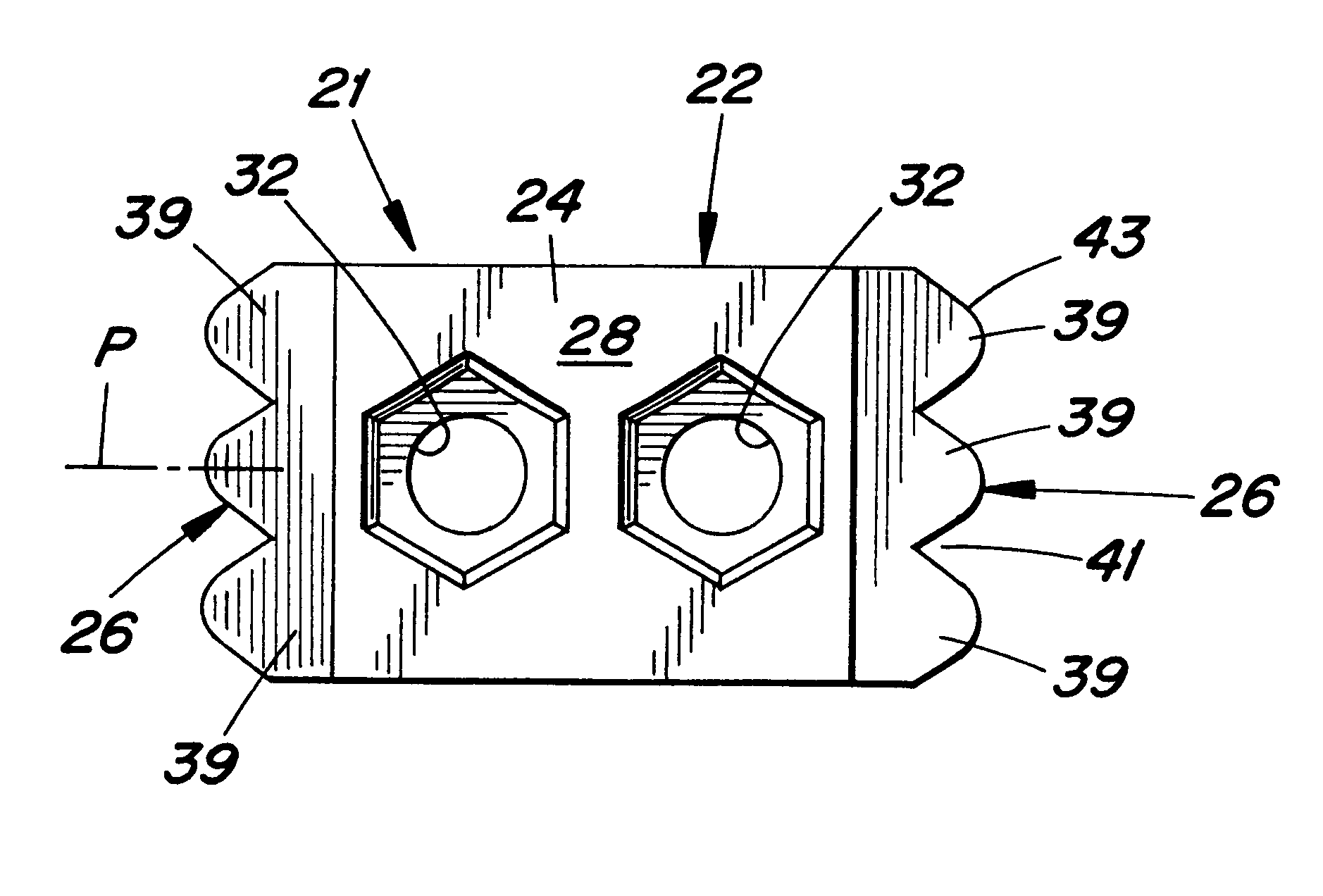
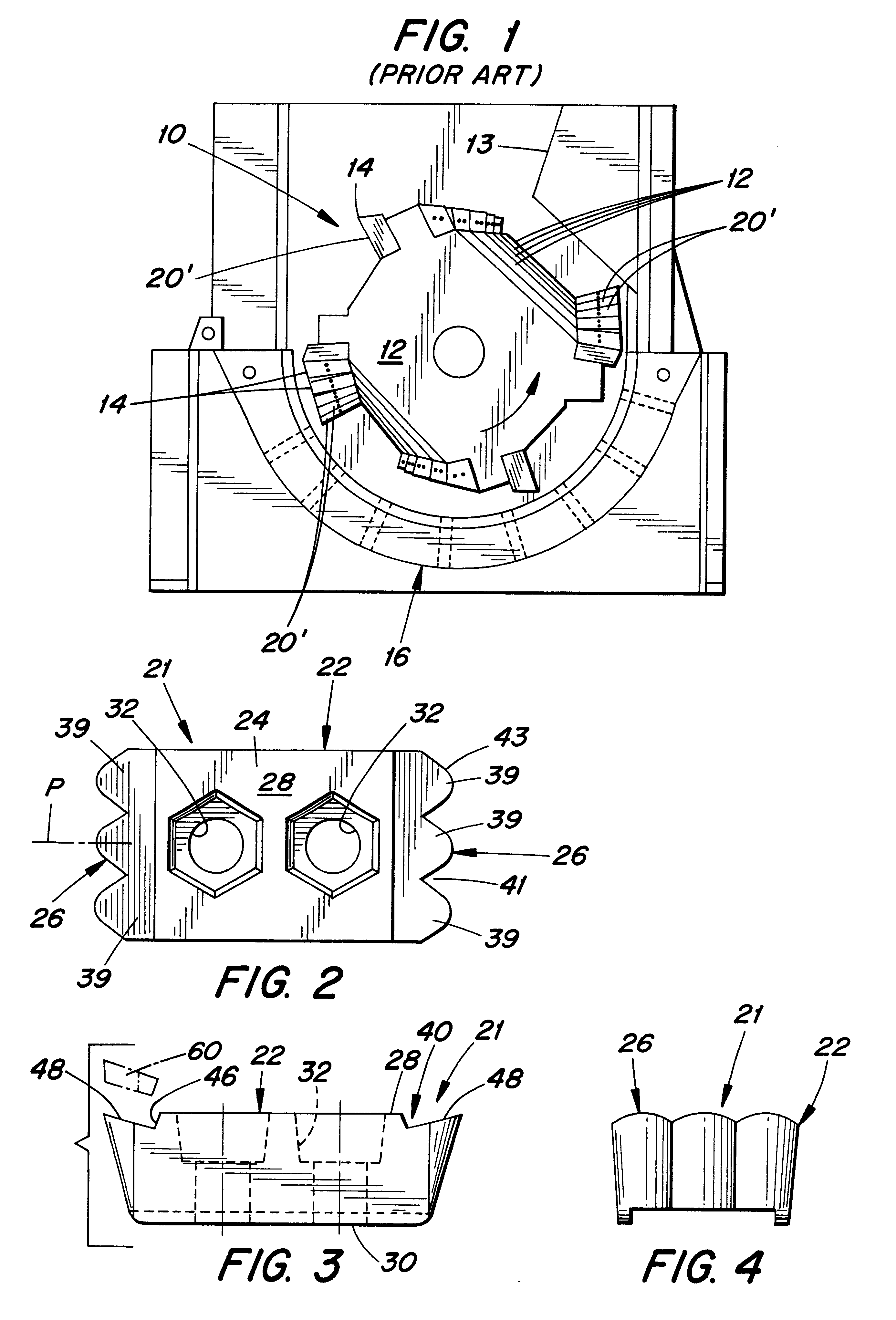
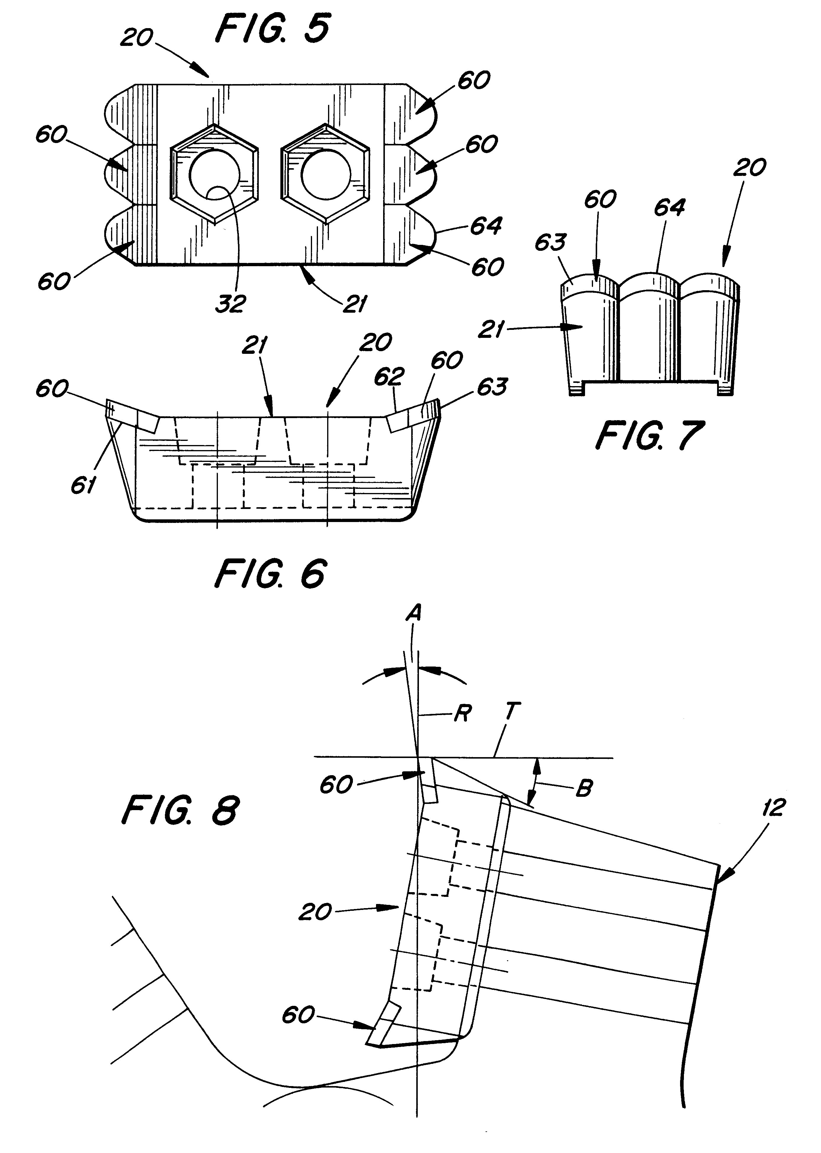
A striker bar 20 (see FIGS. 2-4) according to the present invention comprises a blank or support body 21 and a plurality of cutting tips 60 mounted thereon. The blank is in the form of a generally rectangular steel body 22 having a center mounting portion 24 and first and second identical edge portions 26, 26 disposed at opposite ends of a top surface 28 of the body (see FIGS. 2-4). The body also includes a bottom surface 30. Through-holes 32 are formed through the mounting portion 24 for receiving fasteners to secure the striker bar to a drum or other rotary holder.

The top surface 28 has two grooves 40, each formed between the mounting portion 24 and a respective edge 26. Each groove 40 includes an inner surface 46 and an outer surface 48, the surfaces 46 and 48 oriented at a right angle with one another, whereby the groove is of generally V-shaped cross section as the blank is viewed from the side (see FIG. 3). The outer surface 48 is inclined upwardly and outwardly from a lower e...


PUM


Abstract

A mechanism for disintegrating breakable materials, such as wood, pipes, bricks, etc. includes a rotary drum having striker bars mounted thereon which disintegrate the breakable materials. Each striker bar has a notched cutting edge formed by a row of carbide tips sintered to an edge of a steel body. The cutting edge can be of serrated shape and/or scallop-shape.

Description

BACKGROUND AND OBJECTS OF THE INVENTIONThe invention pertains to an apparatus for disintegrating breakable materials, such as wood, cinder block, brick, pipes, etc., and especially relates to striker bars, which disintegrate breakable materials by being impacted thereagainst.It is conventional to disintegrate or comminute breakable materials such as wood and residual building materials, e.g., bricks, concrete blocks, pipes, for example, by means of so-called hammer hogs, hammer mills, rotor hogs, tub grinders, etc. Those devices operate under the basic principle of rotating a drum to bring grinding elements, carried by the drum, into contact with the materials to be ground. The grinding elements have straight edges that can be hard-faced with carbide, which contact the materials and produce a grinding or crushing action which gradually wears away the materials. As pieces of the materials become ground small enough, they travel through a screen or grating which partially surrounds th...

Claims


Application Information

Patent Timeline
IPC IPC(8): B02C13/00B02C13/28
CPCB02C13/2804
Inventor MONYAK, KENNETH
Owner SANDVIK ROCK TOOLS
Why Eureka
Try Eureka