Self-compensating filament tension control device employing a friction band

a friction band and tension control technology, applied in the direction of filament handling, fluid actuated drum brakes, thin material handling, etc., can solve the problems of large multiplicity, unfavorable hunting or loping of creels, and multiple individual adjustments of creels having variable tension control, etc., to achieve the effect of convenient adjustmen

Inactive Publication Date: 2002-08-20
RJS
View PDF36 Cites 10 Cited by
  • Summary
  • Abstract
  • Description
  • Claims
  • Application Information

AI Technical Summary

Benefits of technology

It is, therefore, an object of the present invention to provide a tension control device for filamentary material which provides for payout of a filamentary material at a uniform tension selected from a substantial range, irrespective of the rate at which the filament is taken up. It is another object of the present invention to provide such a tension control d

Problems solved by technology

Obviously, the problem is greatly multiplied when a creel assembly carrying up to several hundred spools is being used.
In the past, such creels having variable tension control have often required multiple individual adjustments and have not been desirably compact.
In other instances, creels have exhibited undesirable hunting or loping in the form of periodic variations about a desired tension, particularly in high-tension applications.
However, there are several situations in which these tension control devices are not well suited.
It

Method used


Image

  • Self-compensating filament tension control device employing a friction band
  • Self-compensating filament tension control device employing a friction band
  • Self-compensating filament tension control device employing a friction band

Examples


Embodiment Construction

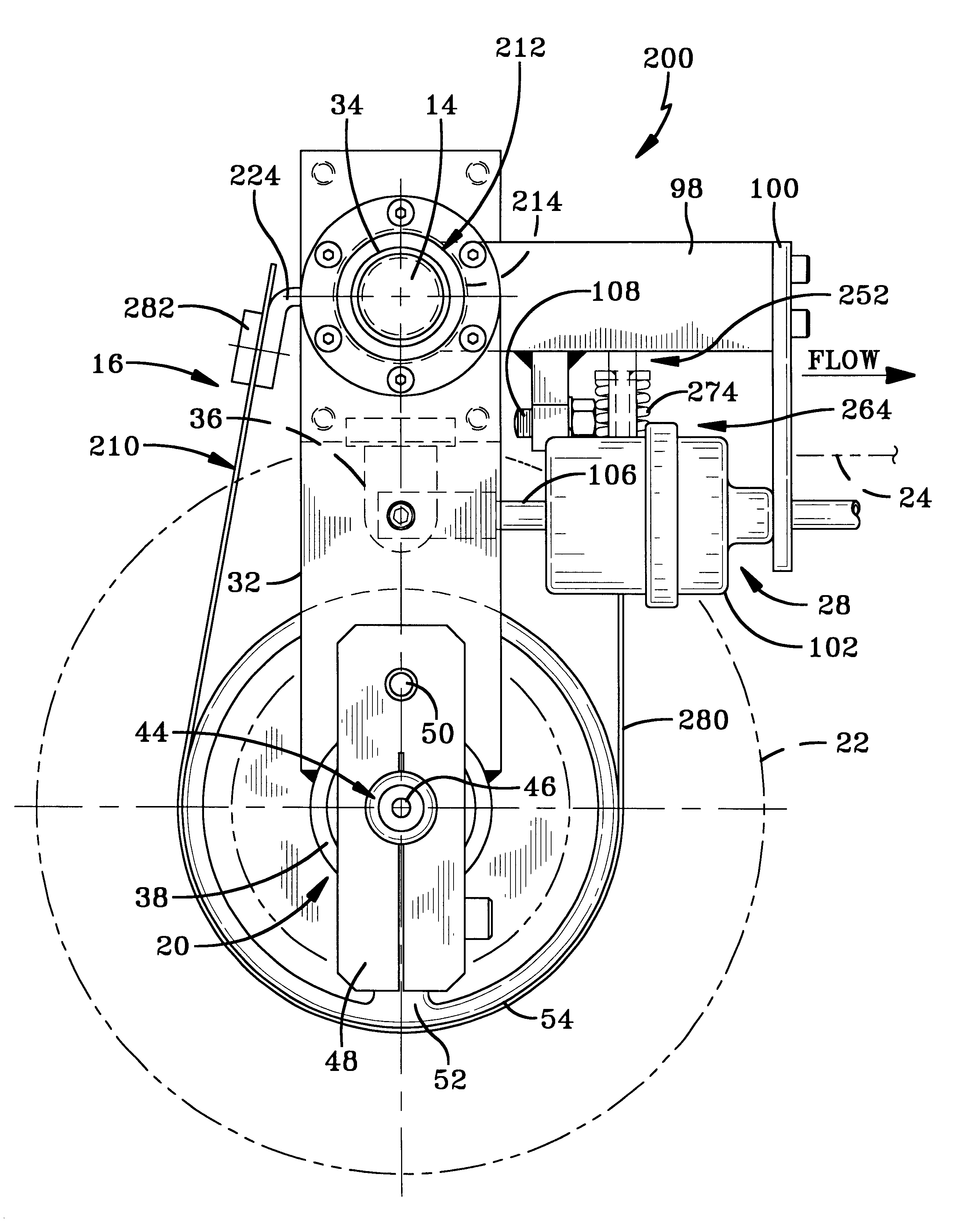
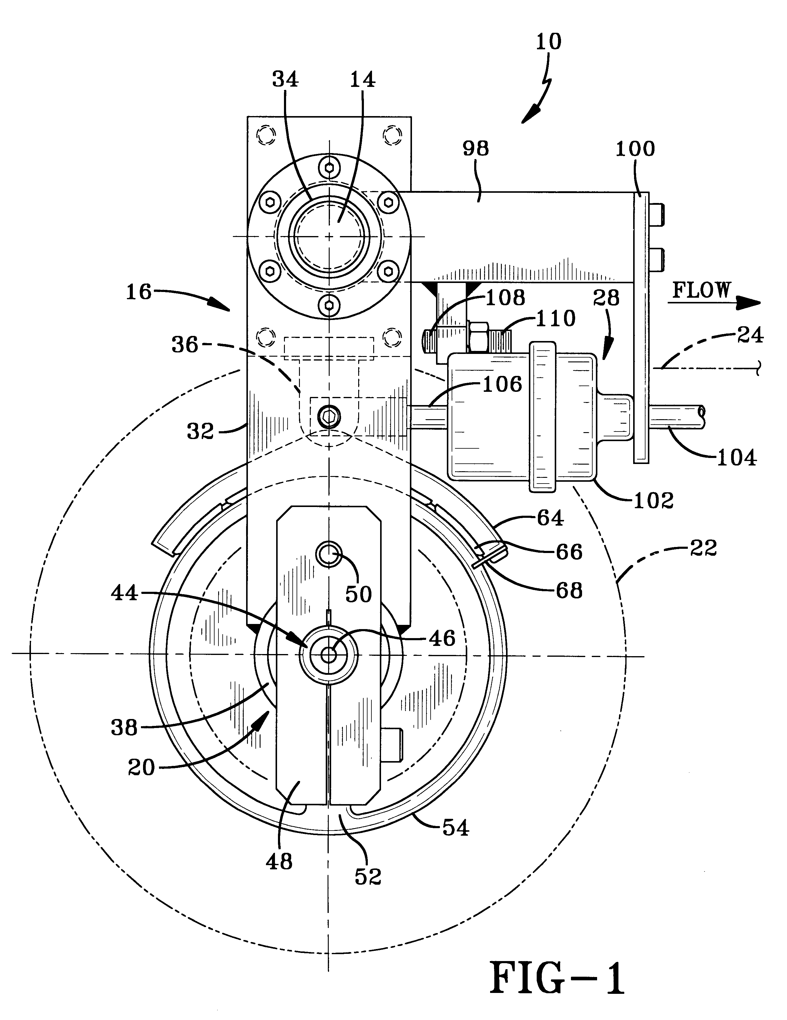
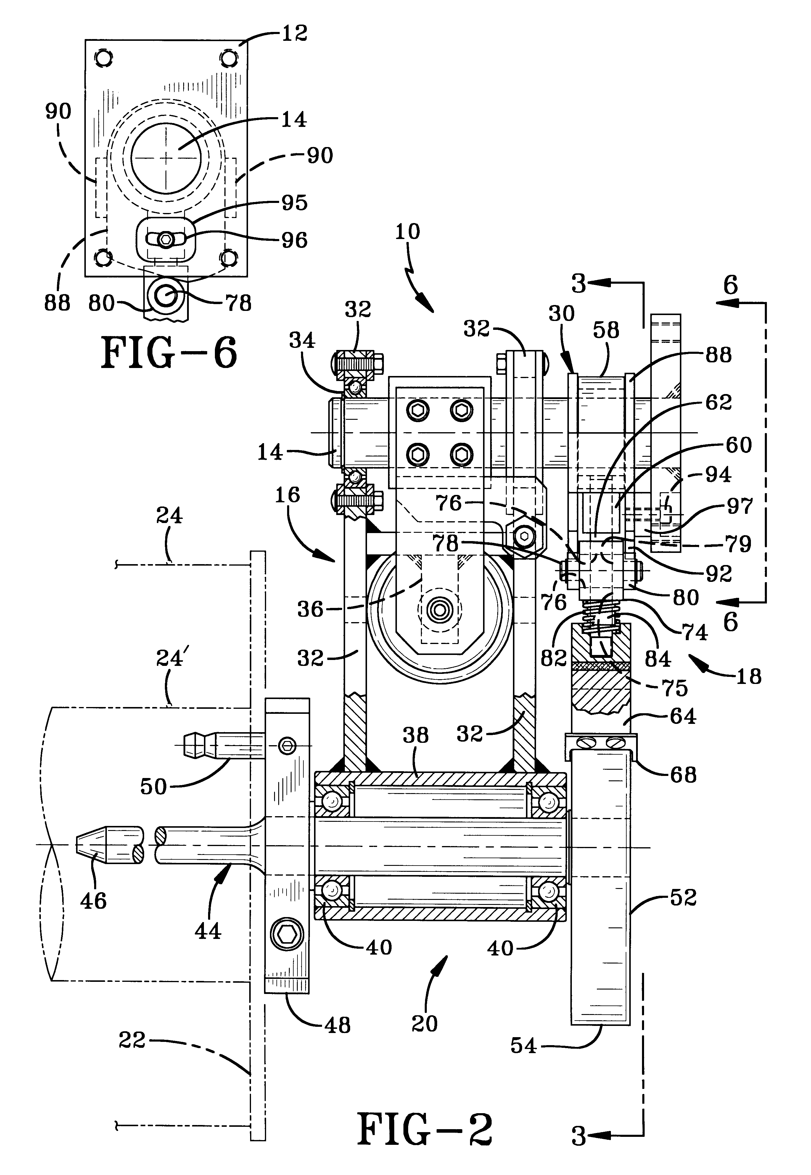
An exemplary self-compensating filament tension control device according to the concepts of the present invention is generally indicated by the numeral 10. As best seen in FIGS. 1, 2, and 6, the tension control device 10 includes a frame support 12 from which a fixed shaft 14 integrally extends. The frame support 12 may be part of a creel or other support structure which is part of a machine that processes individual strands of filamentary material into a finished manufactured item. It will be appreciated that the frame support 12 may also be employed to support multiple devices 10 as needed.

A swing frame assembly, generally indicated by the numeral 16, is pivotably mounted upon a distal end of the fixed shaft 14. Also pivotably mounted upon the fixed shaft 14 is a braking assembly generally indicated by the numeral 18. The braking assembly 18 is shown positioned between the swing frame assembly 16 and the fixed support 12. A spindle assembly, generally indicated by the numeral 20, ...


PUM


Abstract

A self-compensating tension control device for regulating the payout of filamentary material from a spool includes a fixed support and a spindle assembly pivotably mounted to the fixed support, wherein the spindle assembly rotatably carries the spool of filamentary material. A pull-off force imparted by the filamentary material causes angular movement of the spindle assembly and rotation of the spool. A braking assembly mounted to the fixed support and coupled to the spindle assembly applies a braking force corresponding to an angular position of the spindle assembly.

Description

The present invention relates generally to an automatic tension control device for regulating the amount of tension under which a filamentary material is withdrawn from a spool. More particularly, the present invention relates to such a tension control device which tends to maintain substantially constant tension in filamentary materials over variances in operating parameters. More specifically, the present invention relates to such a tension control device which employs a suspended spindle operative with a band brake assembly, thereby tending to maintain substantially constant tension in a filament.Filamentary materials include fibers in single and multiple strands, flat bands, or tubing produced in long lengths and conveniently wound on spools. The various filamentary materials may be either natural or synthetic fibers, glass or metal. Such materials are commonly utilized as reinforcements for plastic or elastomeric compounds or may themselves be fabricated into integral items as ...

Claims


Application Information

Patent Timeline
IPC IPC(8): B65H59/00B65H59/04B65H77/00B65H59/02
CPCB65H59/04B65H59/046B65H2701/37B65H59/24
Inventor SLEZAK, RAYMOND J.
Owner RJS
Why Eureka
Try Eureka