Insert retention mechanism

a retention mechanism and insert technology, applied in the direction of fastening means, screws, fastener tools, etc., can solve the problems of thwarting the removal of the fastener or the spark plug alone, seized the threaded area between the threads of the fastener or the insert, etc., to achieve the effect of superior gripping, easy installation and difficult removal

Inactive Publication Date: 2002-08-27
LOCK N STITCH INC
View PDF45 Cites 61 Cited by
  • Summary
  • Abstract
  • Description
  • Claims
  • Application Information

AI Technical Summary

Benefits of technology

A further object of the present invention is to provide an insert which is not necessarily used in a repair, but instead provides a material of a different characteristic than the surrounding material within which it is threaded which resists dislodgment once installed. For example, the instant invention can be a relatively hard steel threaded into a relatively soft material such as aluminum to provide superior gripping and a more beneficial characteristic with the fastener or spark plug located within the interior threads of the insert.
A further object of t

Problems solved by technology

In some situations, typically harsh operating environments involving corrosion or galvanic attraction between the various components of a system, the mating area between the threads of the fastener or spark plug can become seized

Method used


Image

  • Insert retention mechanism
  • Insert retention mechanism
  • Insert retention mechanism

Examples


Embodiment Construction

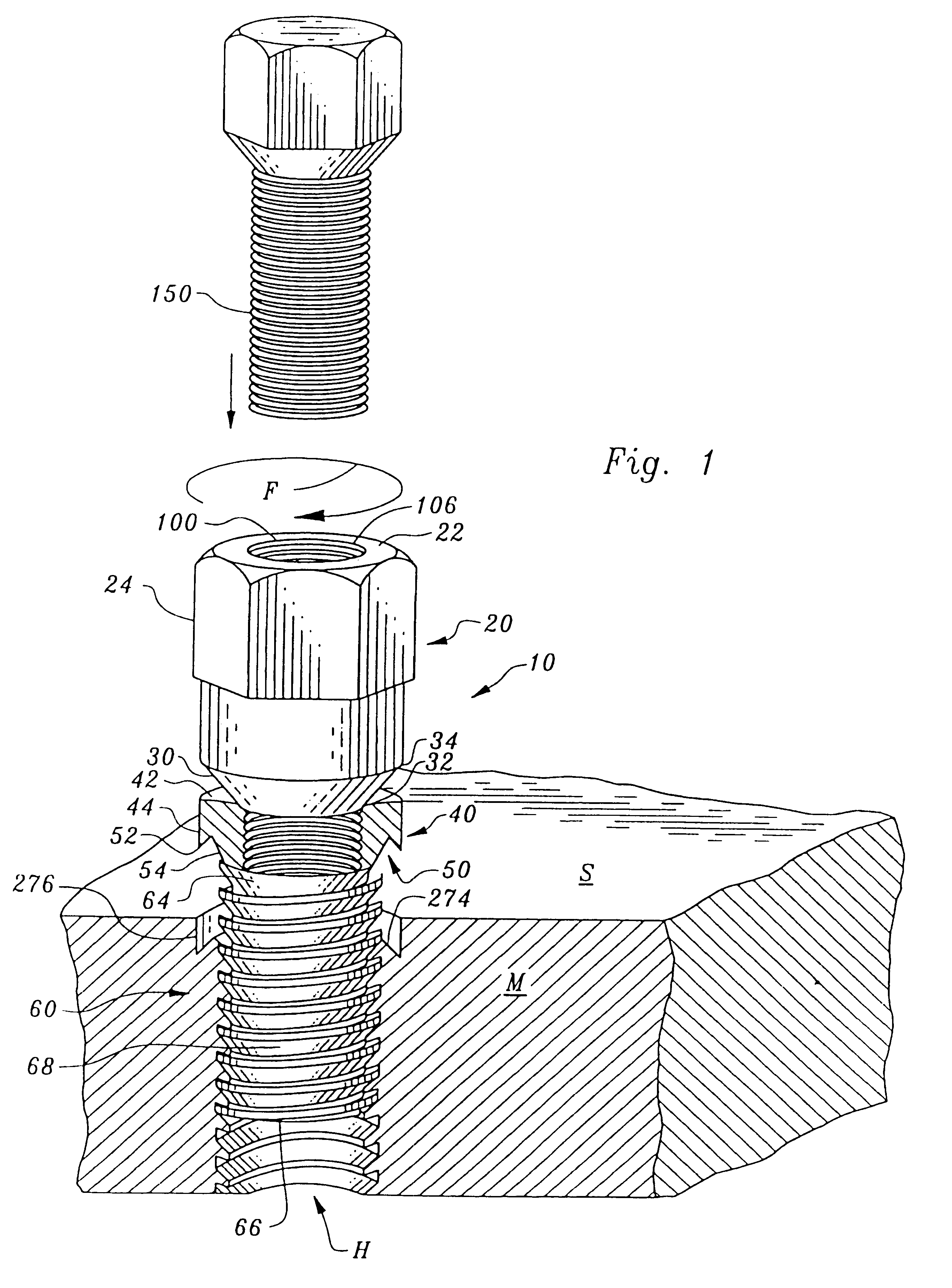
Considering the drawings, wherein like reference numerals denote like parts throughout the various drawing FIGS. , reference numeral 10 is directed to the thread repair insert according to the present invention.

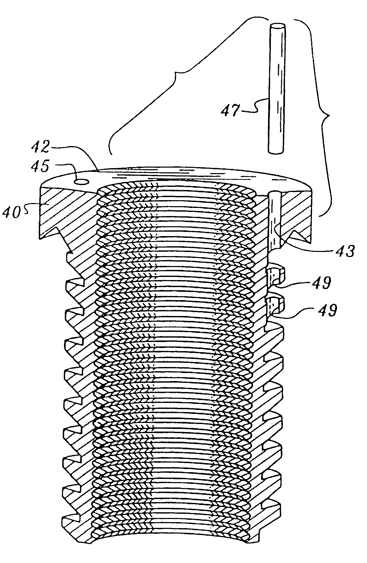
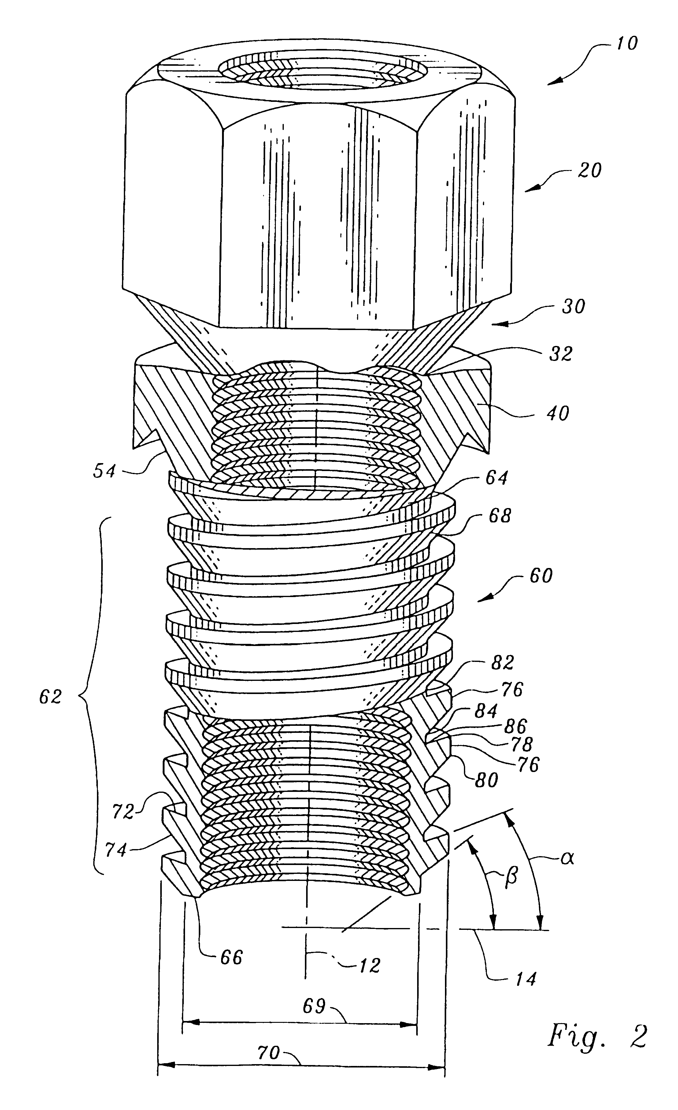
In essence, and referring to FIGS. 1 through 3, the thread repair insert 10 includes an optional drive head 20 at an uppermost portion thereof, a neck 30 below the drive head 20, a shoulder 40 below the neck 30 and a sleeve 60 extending below the shoulder 40. If there is no drive head 20, there is no need for neck 30. The sleeve 60 includes an exterior threaded portion 62 which extends from an upper portion 64 to a bottom portion 66. The exterior threaded portion 62 includes a plurality of threads 68 thereon which include an upper surface 72 and a lower surface 74 which extend upward toward the head 20 from a minor diameter 69 to a major diameter 70. Thus, a crest 76 of each thread 68 is closer to the head 20 than a portion of the thread 68 between adjacent roots 82 at the mi...


PUM


Abstract

An insert for use in allowing spark plugs, fasteners, couplings for hydraulic fittings and pipe threads of a given dimension to be used in a material.

Description

The following invention relates to generally to thread repairs in machinery, particularly cast metal machines. More specifically, the instant invention is directed to a thread repair sleeve having a substantially cylindrical shape and interior and exterior threads used to replace damaged threads in a casting. The focal point is prevention of removal of the insert once installed.Conventional repair techniques for stripped threads includes retapping the thread. While this type of repair is effective in some situations, grossly damaged threads are usually replaced with new threads defining a larger diameter bore. This, of course, necessitates the utilization of a larger fastener within the newly threaded bore which is undesirable particularly when the element to be inserted within the threaded bore is standardized, such as a spark plug.The following prior art reflects the state of the art of which applicant is aware and is included herewith to discharge applicant's acknowledged duty to...

Claims


Application Information

Patent Timeline
IPC IPC(8): F16B37/12F16B39/06F16B37/00F16B39/00
CPCF16B37/125F16B39/06Y10S411/948
Inventor REED, GARY JACK
Owner LOCK N STITCH INC
Why Eureka
Try Eureka