
Mobile communication apparatus

a communication device and mobile technology, applied in the direction of antennas, antenna details, basic electric elements, etc., can solve the problems of user body greatly affecting the antenna characteristics of the user, antennas may be obstacles during communication, and antenna characteristics deterioration

Inactive Publication Date: 2002-08-27
MURATA MFG CO LTD
View PDF12 Cites 19 Cited by
  • Summary
  • Abstract
  • Description
  • Claims
  • Application Information

AI Technical Summary

Benefits of technology

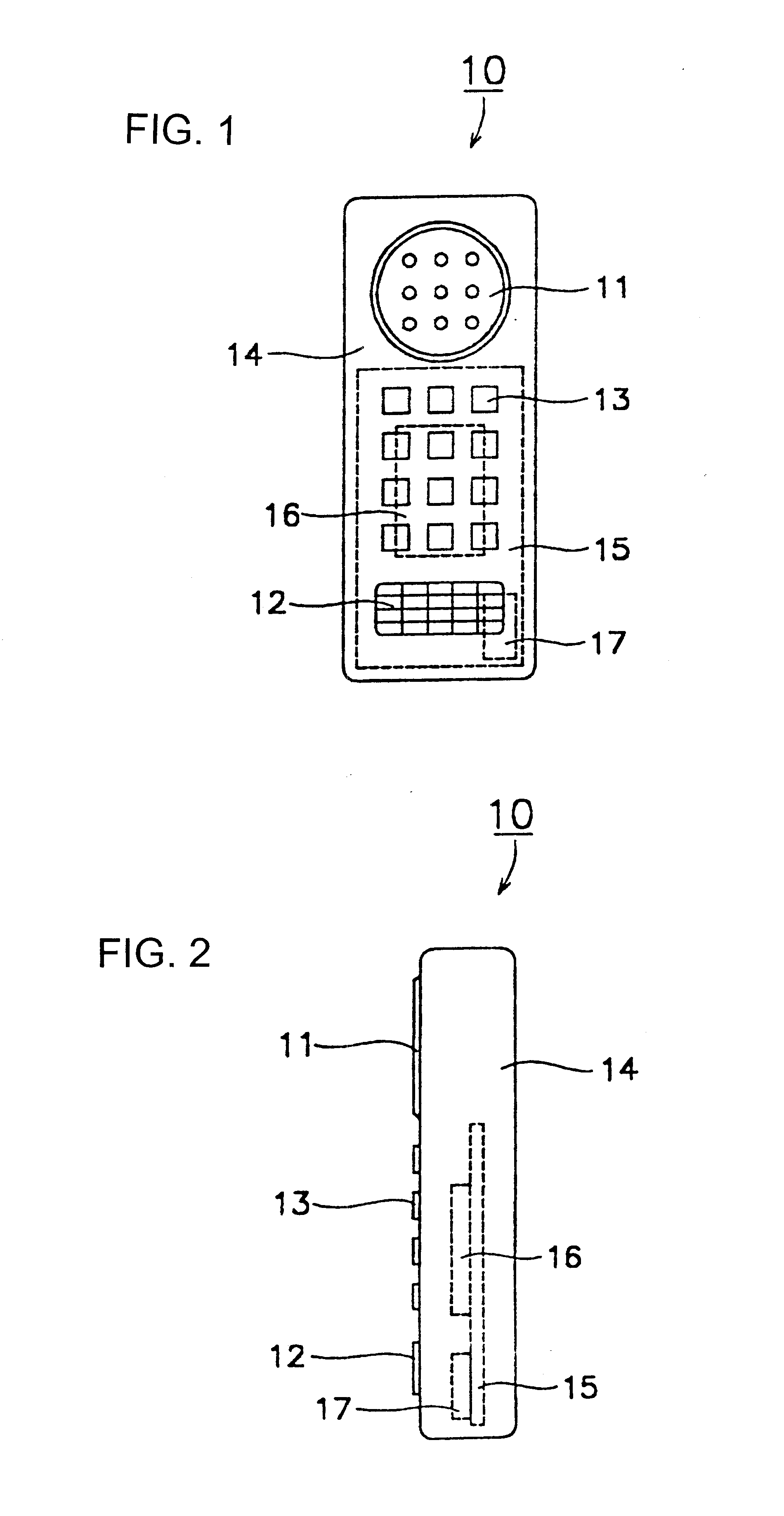
Even when the chip antenna 17 is of a nondirectional type, in the portable telephone 10 configured as described above, since the emission path of an electromagnetic signal transmitted from the chip antenna 17 is away from a person who is holding the portable telephone 10, the transmitted electromagnetic signal is unlikely to be affected by the body of the person and the antenna characteristics of the chip antenna 17 are prevented from deteriorating.

Problems solved by technology

In the portable telephone, however, since the whip antenna is nondirectional, a transmitted electromagnetic signal is affected by the body of the person who is holding the portable telephone during use and therefore the antenna characteristics deteriorate.
Especially in a high-power portable telephone, the user's body greatly affects its antenna characteristics.
To reduce these effects, the whip antenna can be mounted, for example, at the lower part of the portable telephone body; however, since the whip antenna protrudes near the mouth of the person, the antenna may be an obstacle during communication.

Method used


Image

  • Mobile communication apparatus
  • Mobile communication apparatus
  • Mobile communication apparatus

Examples


first embodiment

FIG. 1 and FIG. 2 are a partially transparent elevation and a partially transparent side view of a mobile communication apparatus according to the present invention. In FIGS. 1 and 2, a portable telephone 10 includes a portable telephone body 14 made from, for example, plastic having a receiver 11, a transmitter 12, and dial keys 13, and a chip antenna 17 which is mounted on a circuit board 15 secured at the inside of the portable telephone body 14 and which is electrically connected to an RF section 16 provided on the circuit board 15 in the portable telephone 10 with a transmission line (not shown) on the circuit board 15. The chip antenna 17 is disposed at a place where a transmitted electromagnetic signal is unlikely to be affected by the body of a person who is holding the portable telephone 10, for example, near the transmitter 12.

Even when the chip antenna 17 is of a nondirectional type, in the portable telephone 10 configured as described above, since the emission path of an...

second embodiment

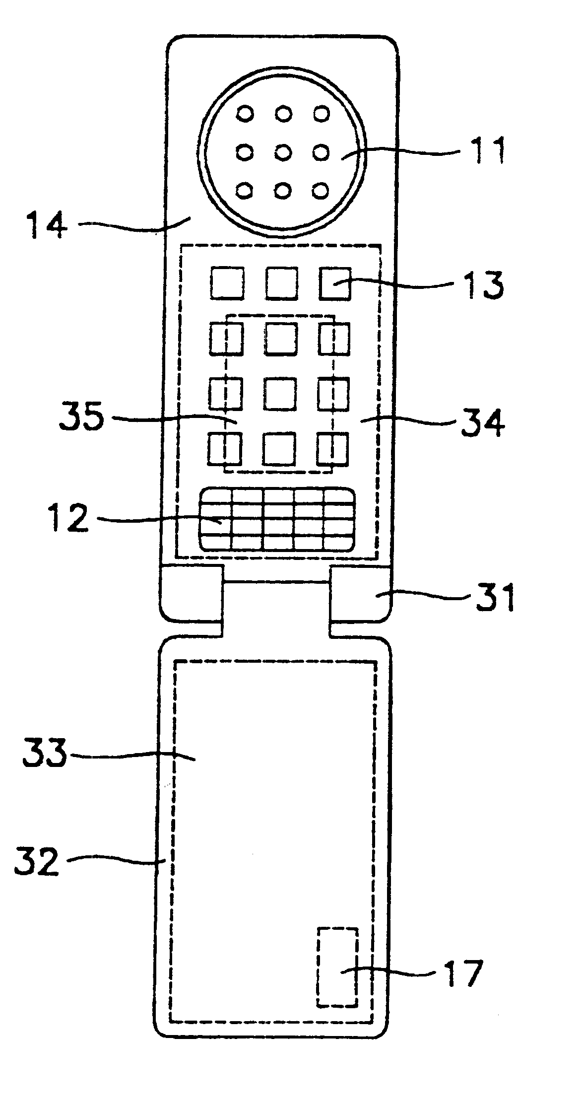
FIG. 8 and FIG. 9 are a partially transparent elevation and a partially transparent side view of a mobile communication apparatus according to the present invention. In FIGS. 8 and 9, a portable telephone 30 is equipped with a cover 32 rotatably connected to the lower part of a portable telephone body 14 by a hinge section 31. With the cover 32 being opened, dial keys 13 are pressed to use the portable telephone 30.

A chip antenna 17 mounted on a circuit board 33 is disposed at a tip of the cover 32. This chip antenna 17 is electrically connected with a lead (not shown) to the RF section 35 of the portable telephone 30 provided on a circuit board 34 secured to the inside of the portable telephone body 14. At the tip of the cover 32, a transmitted electromagnetic signal is unlikely to be affected by the body of a person who is holding the telephone.

As described above, in the second embodiment, by disposing the chip antenna at the tip of the cover in the portable telephone, where a tra...


PUM


Abstract

A portable telephone includes a portable telephone body made from plastic having a receiver, a transmitter, and dial keys, and a chip antenna which is mounted on a circuit board secured at the inside of the portable telephone body and which is electrically connected to an RF section provided on the circuit board in the portable telephone. The chip antenna is disposed near the transmitter at a location where a transmitted electromagnetic signal is unlikely to be affected by the body of a person who is holding the portable telephone.

Description

1. Field of the InventionThe present invention relates to a mobile communication apparatus including a chip antenna for use in mobile communication or in a local area network (LAN).2. Description of the Related ArtIn a portable telephone 50, which is an example of a conventional mobile communication apparatus, as shown in FIGS. 10 and 11, a nondirectional whip antenna 51 is protrusively mounted at the upper part of a portable telephone body 52 and an electromagnetic signal is transmitted or received with the use of this whip antenna 51.In the portable telephone, however, since the whip antenna is nondirectional, a transmitted electromagnetic signal is affected by the body of the person who is holding the portable telephone during use and therefore the antenna characteristics deteriorate. Especially in a high-power portable telephone, the user's body greatly affects its antenna characteristics.To reduce these effects, the whip antenna can be mounted, for example, at the lower part of...

Claims


Application Information

Patent Timeline
Patent Type & Authority Patents(United States)
IPC IPC(8): H01Q1/24H01Q1/36H01Q1/38
CPCH01Q1/24H01Q1/243H01Q1/362H01Q1/38
Inventor TSURU, TERUHISAMANDAI, HARUFUMISHIROKI, KOJIASAKURA, KENJIKANBA, SEIJI
Owner MURATA MFG CO LTD
Learn More