Durable refractory ceramic coating

a technology of refractory ceramics and coatings, applied in the direction of cosmonautic thermal protection, machines/engines, cosmonautic vehicles, etc., can solve the problems of limited rcg's maximum temperature capability and relatively poor rcg resistance to impact, and achieve the effect of higher temperature capability

Inactive Publication Date: 2002-09-03
ECESIS
View PDF18 Cites 29 Cited by
  • Summary
  • Abstract
  • Description
  • Claims
  • Application Information

AI Technical Summary

Problems solved by technology

As a surface coating, RCG has relatively poor resistance to impact; as a silica-based system, RCG's maximum temperature capability is limited to its softening point of about 2,700-2,800.degree. F.

Method used

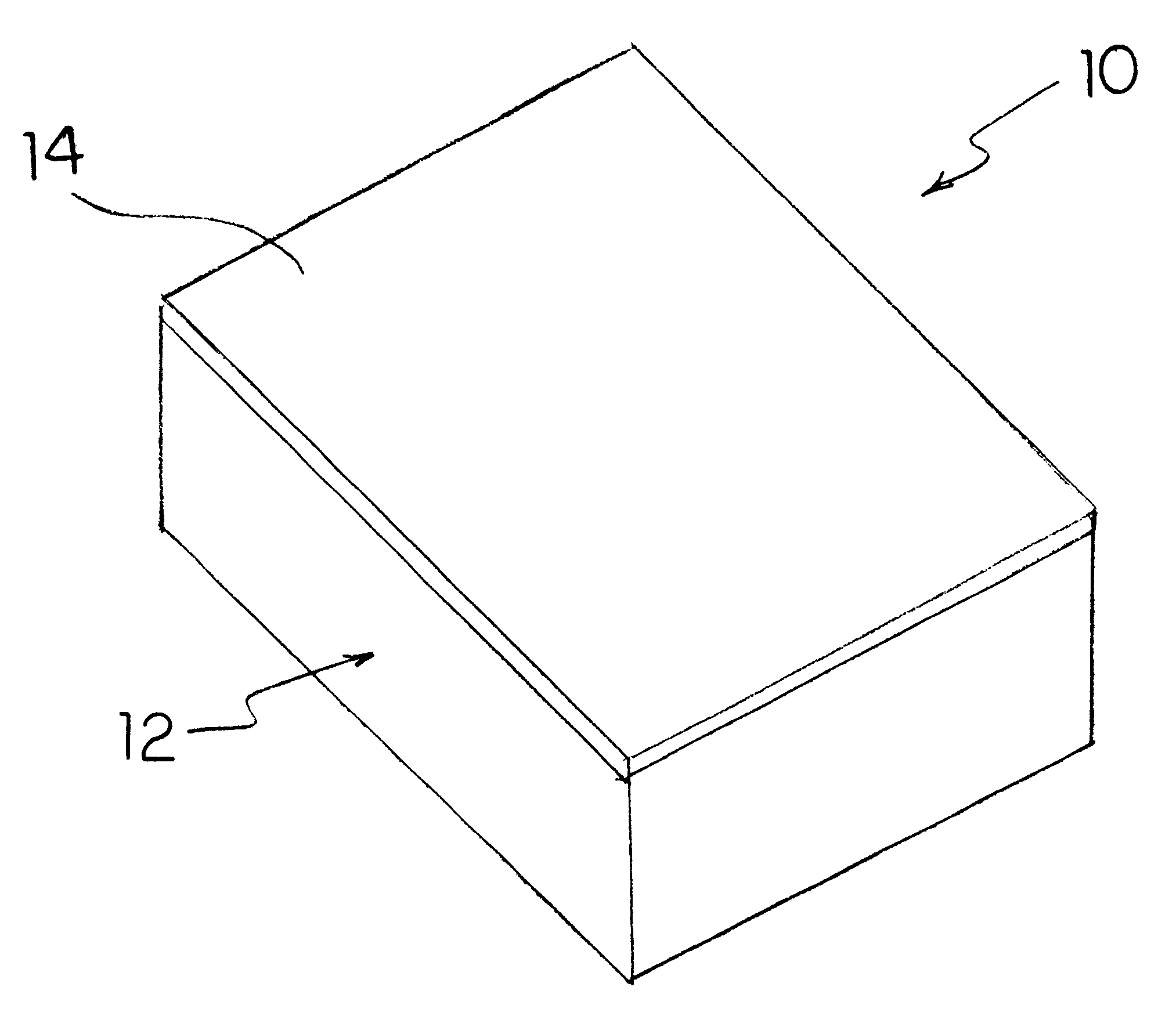
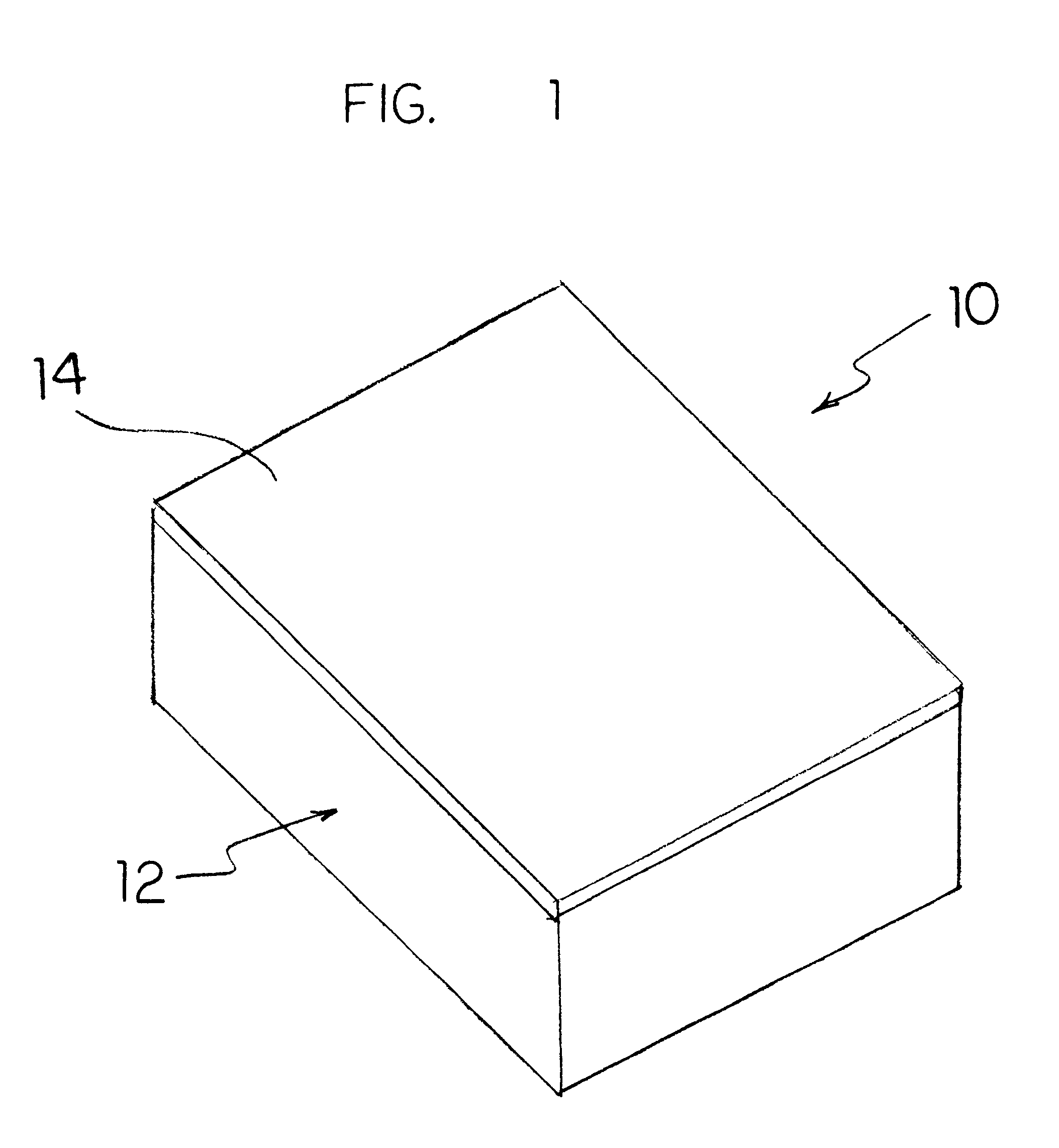
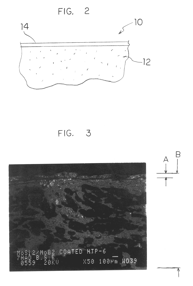

Image

  • Durable refractory ceramic coating
  • Durable refractory ceramic coating
  • Durable refractory ceramic coating

Examples


Embodiment Construction

To make tiles used for the X-33 spacecraft, a slurry was created by using 43% by weight molybdenum silicide powder (100 mesh), 7% by weight boron nitride powder (325 mesh), 2.5% by weight liquid stock solution A, which is a polymer-based binder, and 47.5% denatured ethanol. These materials are combined and jar milled to produce a spray slurry which has a density of 11.5+ / -0.5 pounds per gallon, and a particle size distribution as follows:

The slurry is then sprayed to desired thickness and then dried at temperatures and times specified above.

Products made according to the present invention were tested against the prior art and were shown to have marked increases in thermal performance and durability. In a comparative burner rig test, refractory silicide coatings of the present invention were tested against a NASA Ames TUFI+RCG. Both the present coatings and the NASA coatings were made on a base structure made of HTP 8-22. The TUFI+RCG coating had a weight of 1.07 g / in.sup.2 and the p...


PUM

PropertyMeasurementUnit
temperatureaaaaaaaaaa
melting pointaaaaaaaaaa

Abstract

An article used for thermal protection includes a base structure having at least one surface. The base structure is made of a ceramic oxide material. A silicide coating is formed on the at least one surface of the base structure. The coating comprises a refractory metal and silicon, which together form a silicide. The coating is at least partially diffused into the base structure at the at least one surface.

Description

The present invention relates generally to refractory materials, and more specifically, to insulating materials having refractory ceramic coatings. A base structure is coated with a refractory silicide coating. The coating is made of a refractory metal, i.e., those having a melting point above about 1,650.degree. C., and silicon. The combination of these materials forms a "silicide" coating.DESCRIPTION OF THE RELATED ARTHigh temperature environments such as those found in atmospheric reentry, jet turbine combustion, or rocket propulsion, necessitate the use of thermal protection systems that provide oxidation protection, high emissivity, and resistance to mechanical damage. One example of such a system is the tile used to cover the outer surfaces of the underbody and wings of NASA's Space Shuttle Orbiter. Each tile is a lightweight, fibrous, silica-based rigid fibrous insulation unit with a nominal density of nine (9) pounds per cubic foot (pcf). The tile is made by the assignee of ...

Claims


Application Information

Patent Timeline
Patent Type & Authority Patents(United States)
IPC IPC(8): B64G1/22B64G1/58C04B41/45C04B41/50C23C10/26C23C10/00C23C26/02F01D5/28
CPCB64G1/226B64G1/58C04B41/009C04B41/5071C04B2111/00982C23C10/26C23C26/02F01D5/288F05D2230/90F05D2300/612Y10T428/273Y02T50/60C04B41/4539C04B41/507C04B14/4631C04B30/02
Inventor WITTENAUER, JEROME P.REEVES, SARAH D.BENNER, KENNETH W.YASUKAWA, ROBERT D.
Owner ECESIS
Why Eureka
Try Eureka