Door control system

a door control and control system technology, applied in the field of door control systems, can solve the problems of large burden on the central processor of the door, large number of iterations per second, and relatively rough operation of the door, and achieve the effect of facilitating obstruction detection

Inactive Publication Date: 2002-09-03
WESTINGHOUSE AIR BRAKE CO
View PDF18 Cites 39 Cited by
  • Summary
  • Abstract
  • Description
  • Claims
  • Application Information

AI Technical Summary

Benefits of technology

Another object of the present invention is to provide a control system for a motorized door which provides for smooth motion of the door.
A further object of the present invention is to provide a control system for a motorized door which facilitates obstruction detection.
It is an additional object of the present invention to provide a control system for a motorized door which is consistent with an obstruction detection system that operates very quickly when an obstruction is detected.
Still another object of the present invention is to provide a control system for a motorized door that is capable of handling differing loads and masses of different door configurations.
An additional object of the present invention is to provide a method of reducing the workload of a central processor for a motorized door so that the central processor is free to perform other tasks.

Problems solved by technology

In prior art type door systems, the calculations needed for the iterated feedback loop place a massive burden on the central processor for the door.
To limit this burden, the number of iterations per second is severely limited.
This results in a relatively rough operation of the doors and thereby complicates the detection of obstructions.

Method used


Image

  • Door control system
  • Door control system
  • Door control system

Examples


Embodiment Construction

, particularly, when the detailed description is taken in conjunction with the attached drawing figures and with the appended claims.

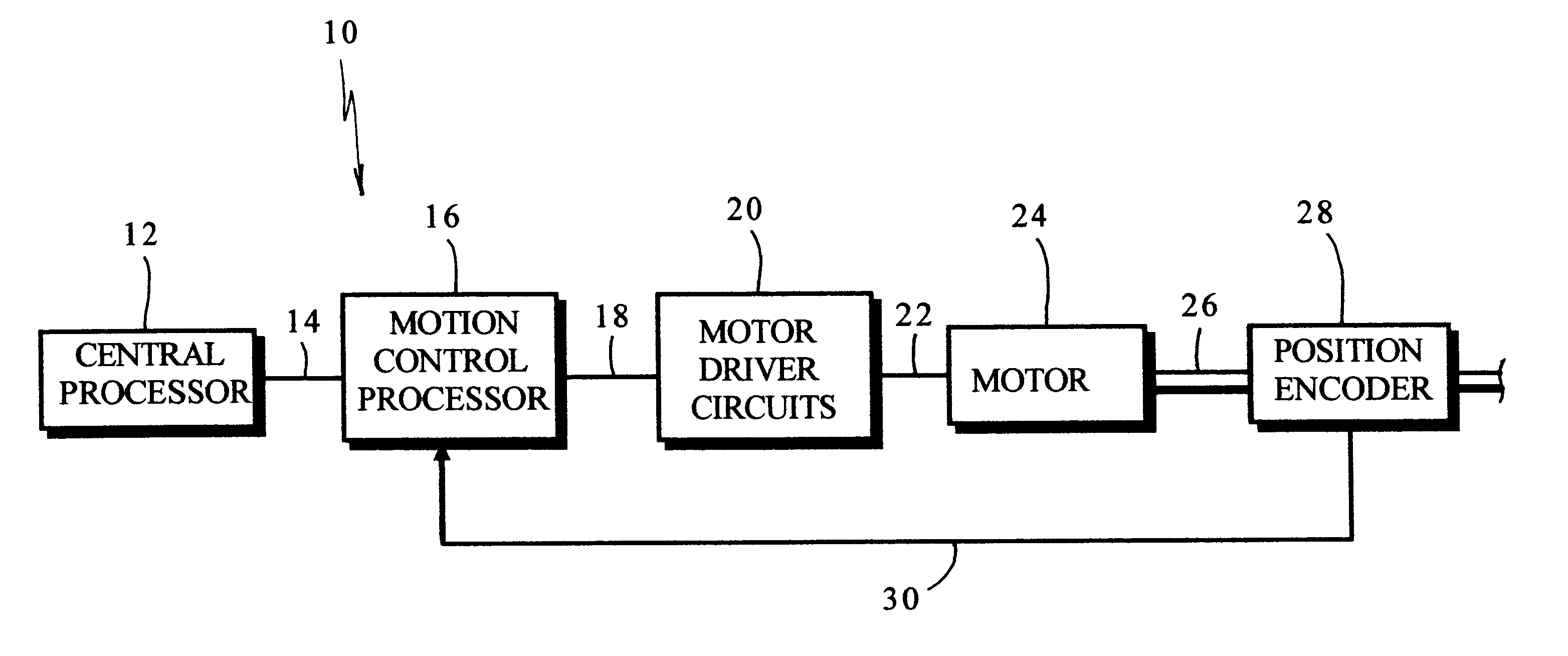
FIG. 1 is a schematic illustration of the presently preferred embodiment of the invention;

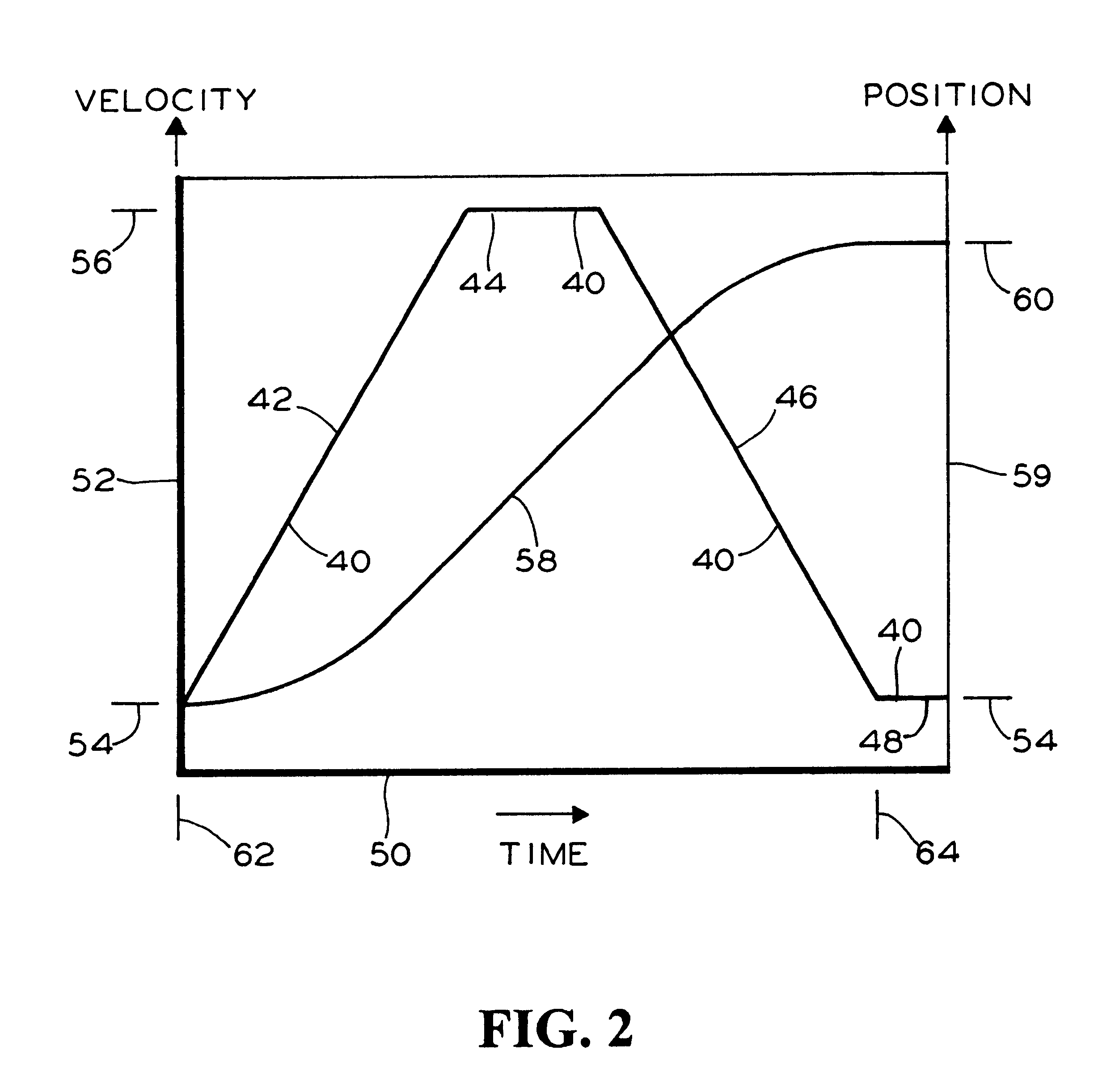
FIG. 2 is a plot showing ideal profiles for door velocity and distance travelled versus time;

FIG. 3 is a flowchart showing the method of an embodiment of the invention; and

FIG. 4 is a flowchart showing the method of the presently preferred embodiment of the invention.

BRIEF DESCRIPTION OF THE PRESENTLY PREFERRED AND VARIOUS ALTERNATIVE EMBODIMENTS OF THE INVENTION

Prior to proceeding to the much more detailed description of the present invention, it should be noted that identical components which have identical functions have been identified with identical reference numerals throughout the several views illustrated in the drawing figures for the sake of clarity and understanding of the invention.

Attention is now directed to FIG. 1 which illustrates an apparatus, gen...


PUM


Abstract

Method of controlling a motorized door by offloading the burden to a separate motion control processor. The method includes generating, in a central processor for the door, one or more signals indicative of a predetermined door speed profile for a stroke of the door. The predetermined door speed profile provides an ideal velocity versus an elapsed time since a beginning of the stroke. The signals are communicated to a motion control processor and the motion control processor also receives door position signals from a position encoder. The motion control processor generates signals indicative of the velocity of the door based on the door position signals and it generates error signals based on discrepancies between the velocity of the door and the ideal velocity. It generates motor control signals based on the error signals and the motor control signals are communicated to the motor of the door.

Description

The present invention relates, in general, to control systems for powered doors and, more particularly, the instant invention relates to a control system for a passenger transit type vehicle door.As is generally well known in the art, control systems for passenger transit vehicle doors must control the forces that are being applied to such doors during both the opening and closing strokes of the doors. At the beginning of a stroke of the door, acceleration forces are required and toward the end of the stroke deceleration forces are required.It is known to employ a position encoder to supply door position information to the control system. Position information is used to obtain velocity information and the velocity of the door is controlled in an iterated feedback loop.In prior art type door systems, the calculations needed for the iterated feedback loop place a massive burden on the central processor for the door. To limit this burden, the number of iterations per second is severely...

Claims


Application Information

Patent Timeline
Patent Type & Authority Patents(United States)
IPC IPC(8): B61D19/00B61D19/02G05B19/416
CPCB61D19/02G05B19/416G05B2219/43036G05B2219/45242
Inventor CALAMATAS, PHILIP J.
Owner WESTINGHOUSE AIR BRAKE CO
Why Eureka
Try Eureka