Receptacle-transfer installation including a deflector member

a technology of deflector and receptacle, which is applied in the direction of conveyors, mechanical conveyors, conveyor parts, etc., can solve the problems of limiting the operating throughput of such an installation, affecting the efficiency of the installation, so as to achieve low cost and high throughput.

a technology of deflector and receptacle, which is applied in the direction of conveyors, mechanical conveyors, conveyor parts, etc., can solve the problems of limiting the operating throughput of such an installation, affecting the efficiency of the installation, so as to achieve low cost and high throughput.

US6446781B1Inactive Publication Date: 2002-09-10SERAC GROUP

Image

  • Receptacle-transfer installation including a deflector member
  • Receptacle-transfer installation including a deflector member
  • Receptacle-transfer installation including a deflector member

Examples


first embodiment

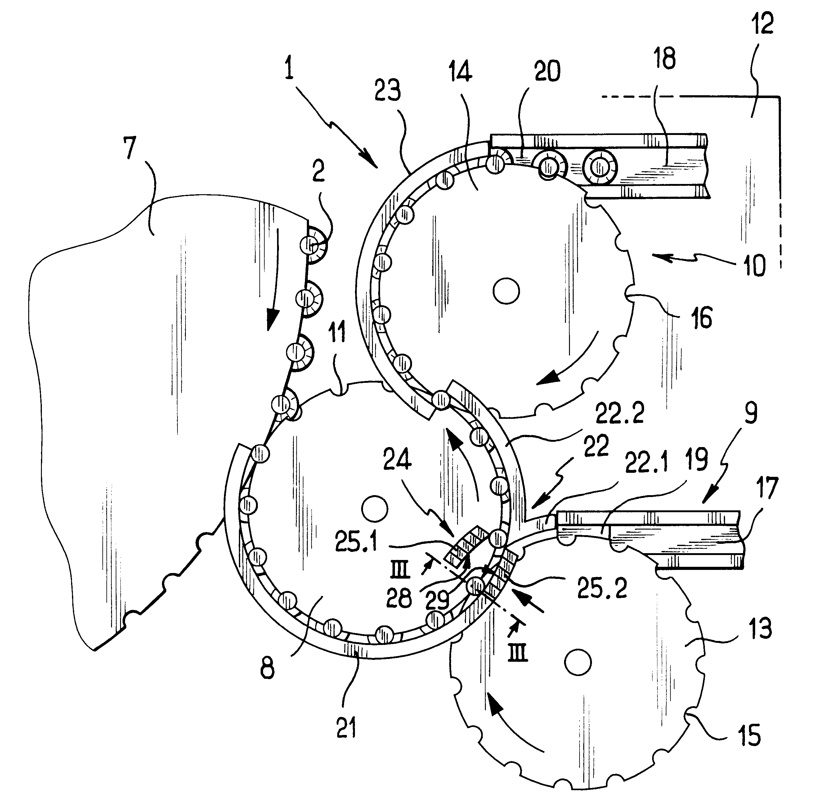
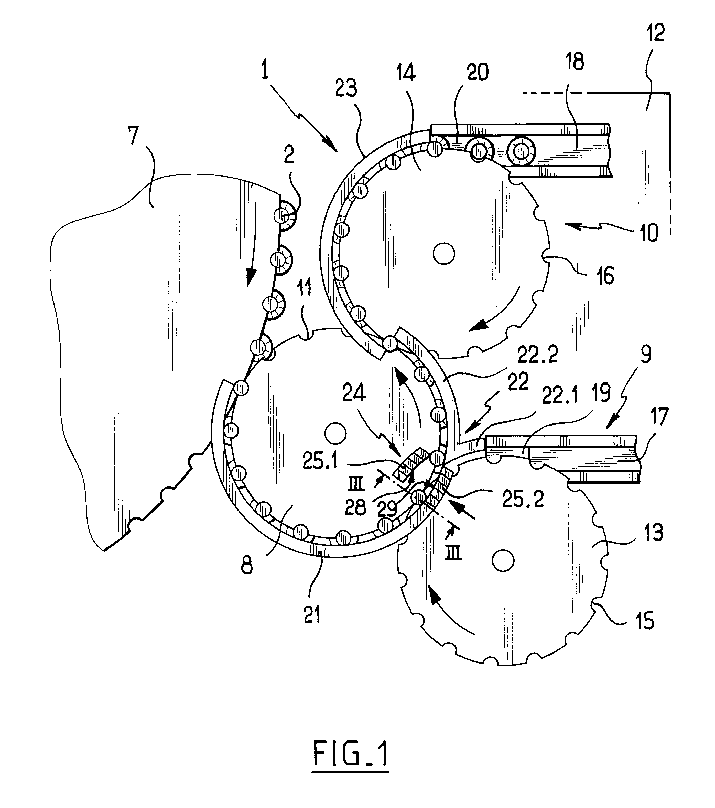
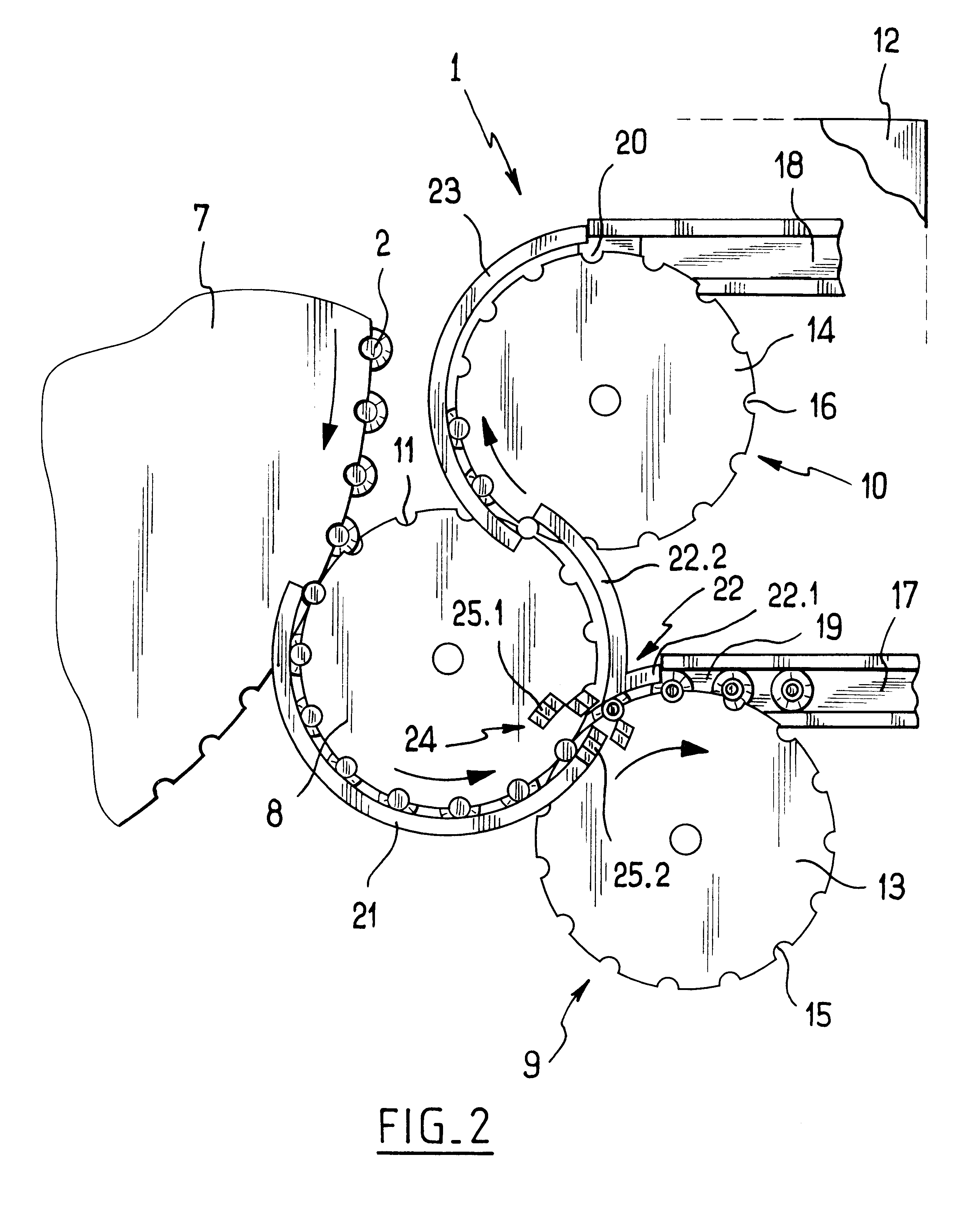
In a first embodiment as shown in FIG. 3, the deflector member 24 comprises two facing rows each of five segments. Each of the segments in one row is referenced 25.1 and each in the other row is referenced 25.2 (only two of the segments are shown in FIG. 3).

Each segment 25.1 is connected to the facing segment 25.2 by a support element 26 associated with an actuator 31 carried by the frame 12 to slide parallel to the plane of the transport starwheels 8 and 13. The facing surfaces of the segments 25.1 and 25.2 define respective guide surfaces 28 and 29. When a facing pair of segments 25.1 & 25.2 are in a first position, the guide surfaces 28 extend the first branch 22.1 of the downstream guide 22 over the upstream transport starwheel 8. When a facing pair of segments 25.1 & 25.2 are in their second position (as shown in FIG. 3), then the guide surfaces 29 connect the upstream guide 21 to the second branch 22.1 of the downstream guide 22. The displacement stroke of the segments 25.1, 2...

second embodiment

the deflector member operates in a manner that is analogous to that of the first embodiment.

Naturally, the invention is not limited to the embodiment described and variants can be made thereto without going beyond the ambit of the invention as defined by the claims.

In particular, facing segments 25.1 & 25.2 can be independent of each other, but under such circumstances it is necessary to provide synchronized control members for the facing segments.

In addition, the segments can be mounted on the frame 12 so as to pivot eccentrically about a vertical axis.

Also, even though the deflector member 24 is described as being made up of two rows of facing segments, the deflector member 24 could be made up of two facing paddles. This embodiment is particularly advantageous when the distance between receptacles on the transport starwheels is relatively great, but that leads to lower rates of throughput than when using receptacles that are very close together.

Although the installation of the inv...


PUM


Abstract

The receptacle transfer installation comprises an upstream transport starwheel adapted to support the receptacles via their collars, a first downstream transport starwheel, a second downstream transport starwheel. An upstream guide extends as far as the first downstream transport starwheel, and a fixed downstream guide having a first branch extending around a portion of the first downstream transport starwheel and a second branch extending around a portion of the upstream transport starwheel between the two downstream transport starwheels. A deflector member is mounted to move between a first position in which the deflector member extends the first branch of the downstream guide and a second position in which the deflector member connects the upstream guide to the second branch of the downstream guide.

Description

The present invention relates to an installation for transferring receptacles each having a neck provided with a collar. By way of example, an installation of this type can be used in a bottling plant.In a bottling plant, it is common practice to provide transfer installations that take receptacles reaching the installation and share them between two outlet paths. For example, such an installation can be placed at the outlet from a carousel for stoppering receptacles in order to direct properly stoppered receptacles to a zone for packaging them in batches, and poorly stoppered receptacles towards a storage zone.Transfer installations are known that comprise a main conveyor belt, a branch conveyor belt, and a deflector member movable between a projecting position in which the deflector member causes receptacles placed on the main conveyor belt to be deflected onto the branch conveyor belt, and a retracted position in which the receptacles remain on the main conveyor belt. Such an ins...

Claims


Application Information

Patent Timeline
10 Sep 2002
Publication
US6446781B1
IPC
B65G47/71; B65G47/68; B65G47/74; B65G47/76; B65G47/84; B65G47/82
CPC
B65G47/71; B65G47/766; B65G47/846
Inventors
DE VILLELE, DAMIEN