Method and apparatus for compensating an optical filter

a technology of compensating device and optical filter, applied in the field of communication, can solve the problems of inherently large form factor, device limitation, and inability to use bragg grating as frequency standard,

Inactive Publication Date: 2002-09-10
II VI DELAWARE INC
View PDF14 Cites 25 Cited by
  • Summary
  • Abstract
  • Description
  • Claims
  • Application Information

AI Technical Summary

Problems solved by technology

This precludes the use of the Bragg grating as a frequency standard absent suitable packaging for compensating the device...

Method used


Image

  • Method and apparatus for compensating an optical filter
  • Method and apparatus for compensating an optical filter
  • Method and apparatus for compensating an optical filter

Examples


Embodiment Construction

A method and apparatus for compensating an optical filter is disclosed. The device substantially maintains the selected center wavelength in the optical filter across a range of operating temperatures. The optical filter may be used in a broad range of applications for one or more optical signals as a filter or a frequency reference. The device exhibits a low form factor and precise tuning capability.

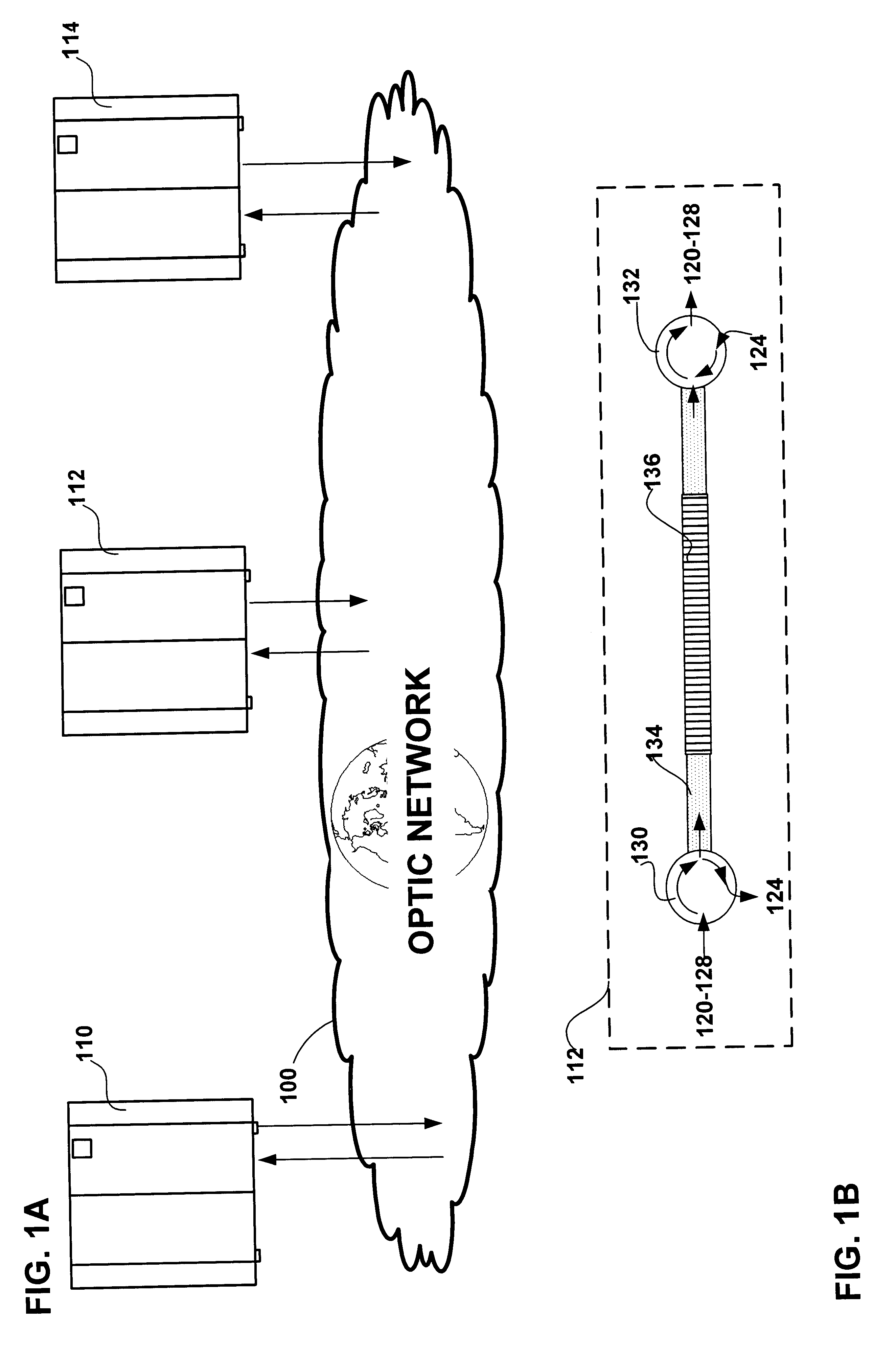
FIG. 1A shows a number of users 110-114 connected to a wavelength division multiplexed (WDM) optical network 100. A WDM network includes a plurality of channels multiplexed on a single optical fiber, each with a specific center wavelength. Individual users may interface with the network through add / drop multiplexers (mux) of varying degrees of complexity depending on the number of channels to be handled. An add / drop mux may also be used as part of the fiber conditioning equipment on the fiber links which join users. Over long haul optic networks fiber conditioning includes amplification...


PUM


Abstract

A method and apparatus for compensating an optical filter is disclosed. The device substantially maintains the selected center wavelength in the optical filter across a range of operating temperatures. In an embodiment of the invention an optical filter is disclosed for filtering a selected channel among a plurality of multiplexed channels of an optical communication. The optical filter includes an optical fiber and an elongate housing. The optical fiber has a first side and a second side and a filter portion intermediate the first side and the second side, and the optical fiber for transmitting the multiplexed optical communication and the filter portion for filtering the selected channel. The elongate housing includes exposed end portions through which the optical fiber extends. The optical fiber is affixed at each exposed end portion. The exposed end portions exhibit between them a negative coefficient of thermal expansion sufficient to generate strains on the filter to substantially stabilize a filtered wavelength to substantially correspond with the selected channel during temperature variations. In an alternate embodiment of the invention the elongate housing is defined about a longitudinal axis and including a first anchor pad and a second anchor pad to which the filter portion is affixed. At least one of the anchor pads is at least initially movable in a plane intersecting the longitudinal axis to vary a strain on the filter portion to tune a center wavelength of the selected channel. In another embodiment of the invention an optical filter for filtering an optical signal is disclosed. In still another embodiment of the invention a method for compensating an optical filter is disclosed.

Description

1. Field of InventionThis invention relates generally to communications, and more particularly, to compensating devices for optical filters.2. Description of the Related ArtThe telecommunications network serving the United States and the rest of the world is presently evolving from analog to digital transmission with ever increasing bandwidth requirements. Fiber optic cable has proved to be a valuable tool, replacing copper cable in nearly every application from large trunks to subscriber distribution plants. Fiber optic cable is capable of carrying much more information than copper with lower attenuation.Currently this expansion of bandwidth is being accomplished by what is known as "wavelength division multiplexing" (WDM), in which separate subscriber / data sessions may be handled concurrently on a single optic fiber by means of modulation of each of those subscriber datastreams on different portions, i.e. channels, of the light spectrum. WDM is therefore the optical equivalent of ...

Claims


Application Information

Patent Timeline
IPC IPC(8): G02B6/34
CPCG02B6/0218
Inventor BETTMAN, R. BRADXIE, PINGCHEN, PETER ZUPEI
Owner II VI DELAWARE INC
Why Eureka
Try Eureka