Method of hot-rolling metal pieces

a metal piece and hot rolling technology, applied in the direction of rare end control devices, roll mill control devices, manufacturing tools, etc., can solve the problem of inability to thread the leading end of the succeeding metal block through

Inactive Publication Date: 2002-09-17
KAWASAKI STEEL CORP
View PDF19 Cites 10 Cited by
  • Summary
  • Abstract
  • Description
  • Claims
  • Application Information

AI Technical Summary

Benefits of technology

As described above, just when the joining devices are shifted to a state such that the leading end of the succeeding metal block can be threaded therethrough, the succeeding metal block is threaded. The feeding of the succeeding metal block may be restarted just when the joining devices are shifted to a state such that the leading end of the succeeding metal block can be threaded therethrough, or may be restarted somewhat earlier than the threading enabling state will be brought about. The succeeding metal block may be temporarily stopped until the feeding is restarted, or may be on oscillation standby, that is, it may move back and forth so that the temperature do not locally fall only in the portion in contact with the roller. The succeeding metal block may be fed at a substantially low speed while the joining devices are shifting to the leading end threading state.

Problems solved by technology

Regarding the succeeding metal block that is not joined or is incompletely joined, if the devices (the joining unit and a treatment unit such as a deburring device) concerned with joining remain in a joining state, the leading end of the succeeding metal block that is not joined or that the incomplete joint resulted in being broken during traveling, after the joining operation is aborted, is at a risk of sticking in the interior of the devices concerned with joining and making it impossible for the leading end of the succeeding metal block to be threaded therethrough.

Method used


Image

  • Method of hot-rolling metal pieces
  • Method of hot-rolling metal pieces
  • Method of hot-rolling metal pieces

Examples


example 2

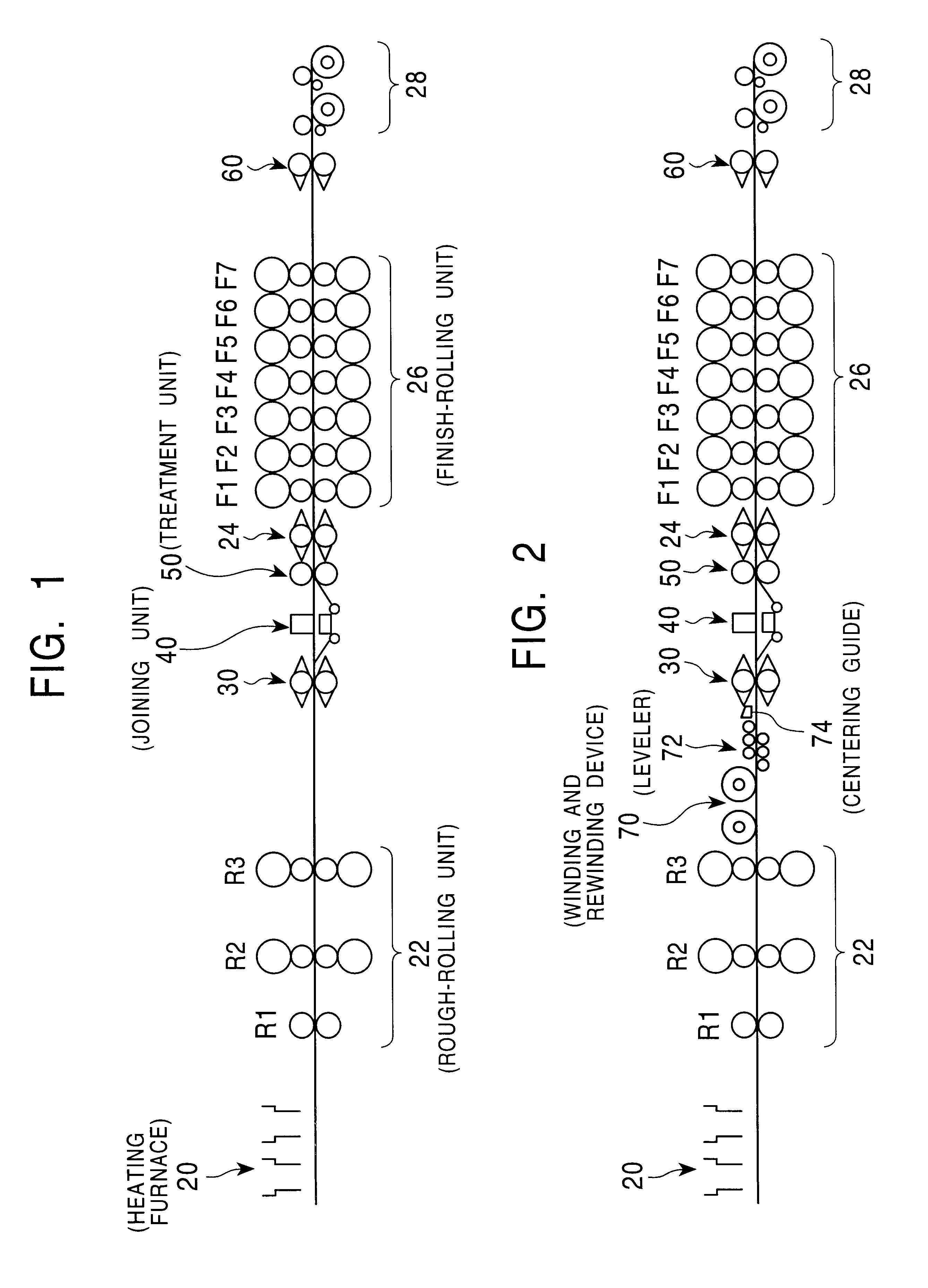
It is assumed that an operation of joining the tail end of the first metal block and the leading end of the second metal block of four blocks to be joined was stopped during endless rolling (the first to fourth are low-carbon steel blocks of 4.0.times.1000 mm).

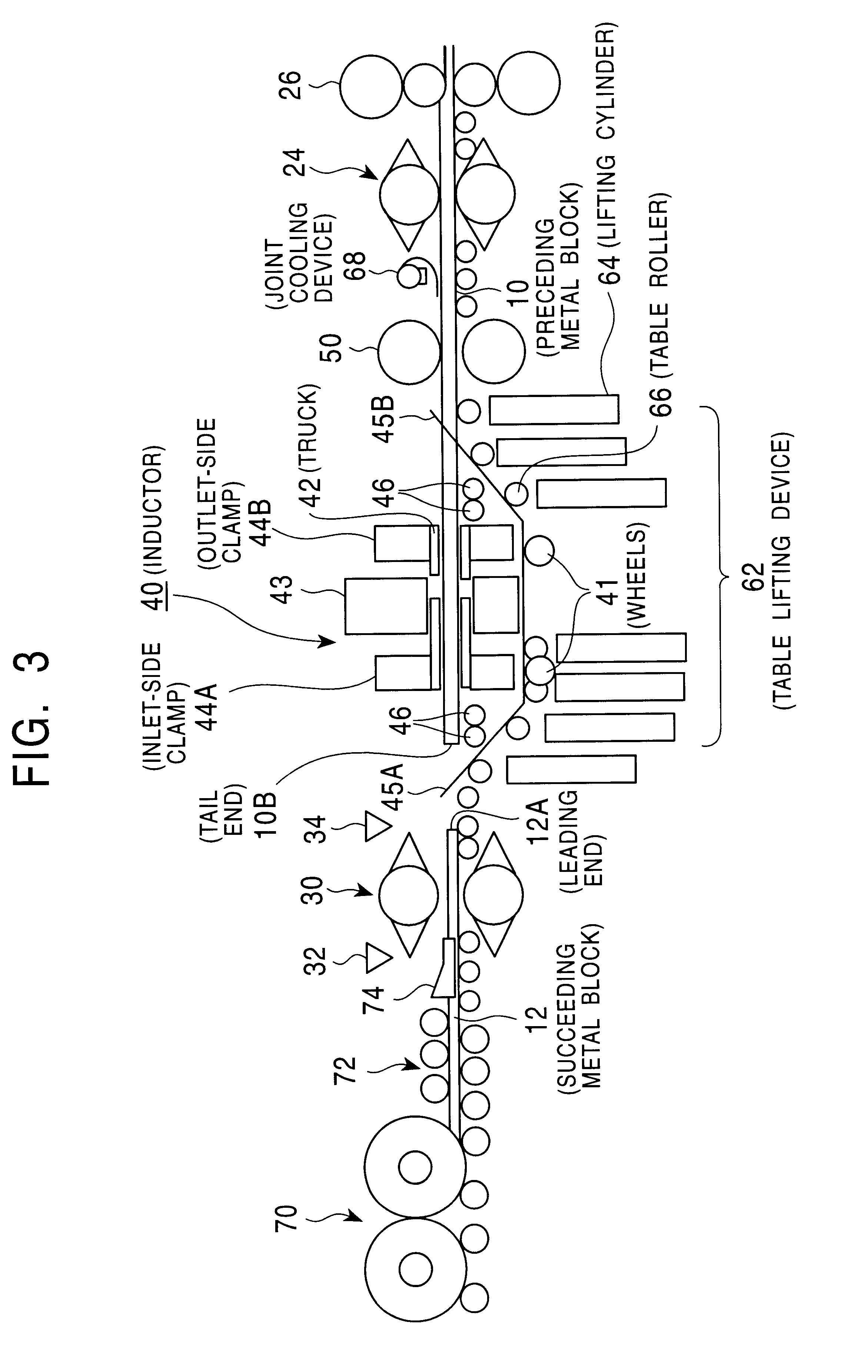
When the joining operation is aborted, the travel of the joining unit 40 and the feeding of a succeeding metal block 12 are temporarily stopped in synchronized velocity. When the joining operation is aborted, the leading end 12A of the succeeding metal block (second) stopped at a position 8.0 m shifted from the starting position (reference position) in the travel zone of the joining unit 40, as shown in FIG. 8. Subsequently, in a manner similar to that in Example 1, the joining unit 40 moved and stopped at the position 13.50 m, called an intermediate position, so that the relative relationship between the travel stop position of the joining unit 40 and the position of the lifting table be appropriate (Step 270), and the table ...

example 3

It is assumed that the tail end of the second metal block and the leading end of the third metal block of four blocks to be joined were incompletely joined during continuous hot rolling (the first is a low-carbon steel block of 1.2.times.1000 mm, the second is a low-carbon steel block of 1.0.times.1000 mm, the third is a low-carbon steel block of 1.0.times.1000 mm, and the fourth is a low-carbon steel block of 1.2.times.1000 mm).

When joining is incomplete, the joining unit 40 travels to the most downstream end of the travel zone in synchronization with the feeding speed of a preceding metal block 10 and a succeeding metal block 12, and stops there. Furthermore, a command to stop removing defective joint portions (burrs) is issued from the control unit 88 to the treatment unit 50. In response to this command, the treatment unit 50 remains in a cutting standby state (a state shown in FIG. 22), and does not perform a cutting operation. Subsequently, the preceding metal block 10 is auto...

example 4

It is assumed that the tail end of the first metal block and the leading end of the second metal block of four blocks to be joined be joined incompletely during endless rolling (the first to fourth are low-carbon steel blocks of 4.0.times.1000 mm).

Subsequent operations of the joining unit, the treatment unit, and the crop shear are the same as those in Example 3. FIG. 35 shows examples of rolling schedules for the second metal block before and after the joint is cut. FIG. 36 shows target thicknesses of the hot-rolled products.

In Example 4, the second metal block, which serves as a succeeding metal block after the joining trouble arises, was finish-rolled to the initially set thickness of 4.0 mm, and the third and fourth metal blocks were then joined and subjected to continuous rolling.

While the present invention is applied to hot rolling for metal blocks in the above description, it is obvious that the present invention is not applicable only to this, but is similarly applicable to ...


PUM

PropertyMeasurementUnit
thicknessaaaaaaaaaa
thicknessaaaaaaaaaa
thicknessaaaaaaaaaa

Abstract

The present invention eliminates the need to stop the operation of a line even when trouble arises before, during, or after an operation of joining metal blocks in hot rolling. According to a specific solving means of the present invention, when a succeeding metal block is to be subjected to hot finish rolling in succession to a preceding metal block after the leading end of the succeeding metal block is joined to a tail end 10B of the preceding metal block on the inlet side of a finish rolling mill 26, it is determined before and after joining whether or not endless rolling is impossible. When it is impossible, joining is aborted, and the succeeding metal block 12 is temporarily stopped, is fed again after the tail end 10B of the preceding metal block moves out of the finish rolling mill 26, and is finish-rolled under the conditions set for batch rolling. When joining was not performed successfully, a joint 11 is cut between a joining unit and the finish rolling mill 26, and the rolled material is bitten by the finish rolling mill set for batch rolling.

Description

The present invention relates to a hot rolling method for metal blocks, and more particularly, relates to a metal block hot rolling method for joining several to several tens of metal blocks, such as sheet bars, slabs, billets, or blooms, and subjecting the metal blocks to continuous rolling.In a conventional metal block hot rolling line, metal blocks to be rolled are individually subjected to heating, rough-rolling, and finish-rolling, and are finished as hot-rolled strips having a desired thickness. In such a batch rolling method, however, the line is inevitably stopped due to poor biting of rolled materials. Moreover, the yield is significantly decreased due to odd shapes of the leading end and the tail end of the rolled materials.For this reason, an endless rolling method has been recently adopted in which the tail end and the leading end of metal blocks to be rolled are coupled (hereinafter referred to as "joined") in advance of finish-rolling, and the metal blocks are continuo...

Claims


Application Information

Patent Timeline
Patent Type & Authority Patents(United States)
IPC IPC(8): B21B1/26B21B15/00B21B39/02B21B45/00B21B39/12B21B37/16B21B37/26B21B1/28B21B1/24
CPCB21B1/26B21B15/0007B21B15/0085B21B1/28B21B37/26B21B39/12B21B45/00B21B2015/0014B21B2201/08B21B2201/10
Inventor HIRABAYASHI, TAKESHIISOYAMA, SHIGERUYAMASAKI, TAKAHIRONIKAIDO, HIDEYUKI
Owner KAWASAKI STEEL CORP
Why Eureka
Try Eureka