Constrained layer damped steel baffle

a technology of steel baffles and steel plates, applied in the direction of mechanical equipment, machines/engines, non-fuel substance addition to fuel, etc., can solve the problems of high cost and less than desirable in most cases, and achieve the effect of reducing the cost of the effect of fuel consumption

Inactive Publication Date: 2002-09-24
DANA AUTOMOTIVE SYST GRP LLC
View PDF10 Cites 39 Cited by
  • Summary
  • Abstract
  • Description
  • Claims
  • Application Information

AI Technical Summary

Problems solved by technology

While many of the attempted efforts have been laudable, their benefits have often been costly and less than desirable in most cases.

Method used


Image

  • Constrained layer damped steel baffle
  • Constrained layer damped steel baffle
  • Constrained layer damped steel baffle

Examples


Embodiment Construction

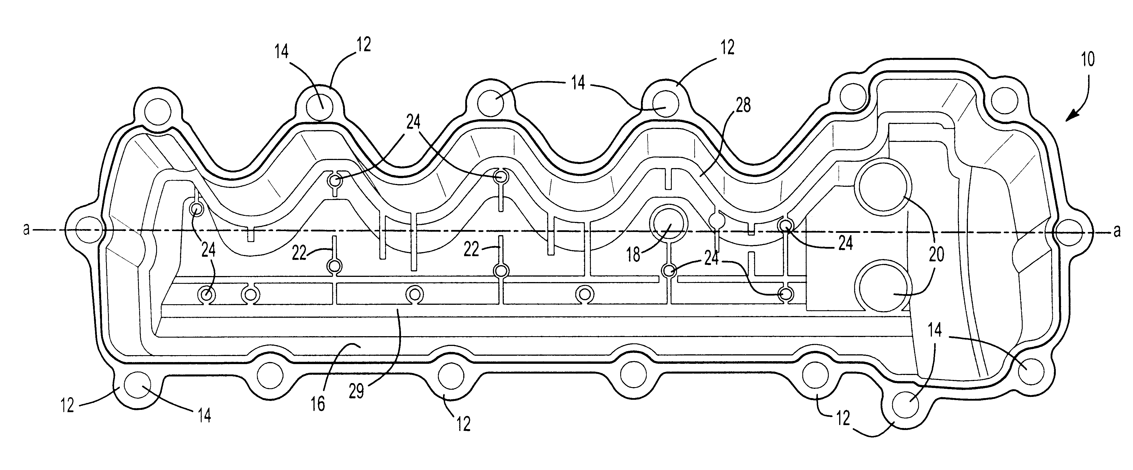
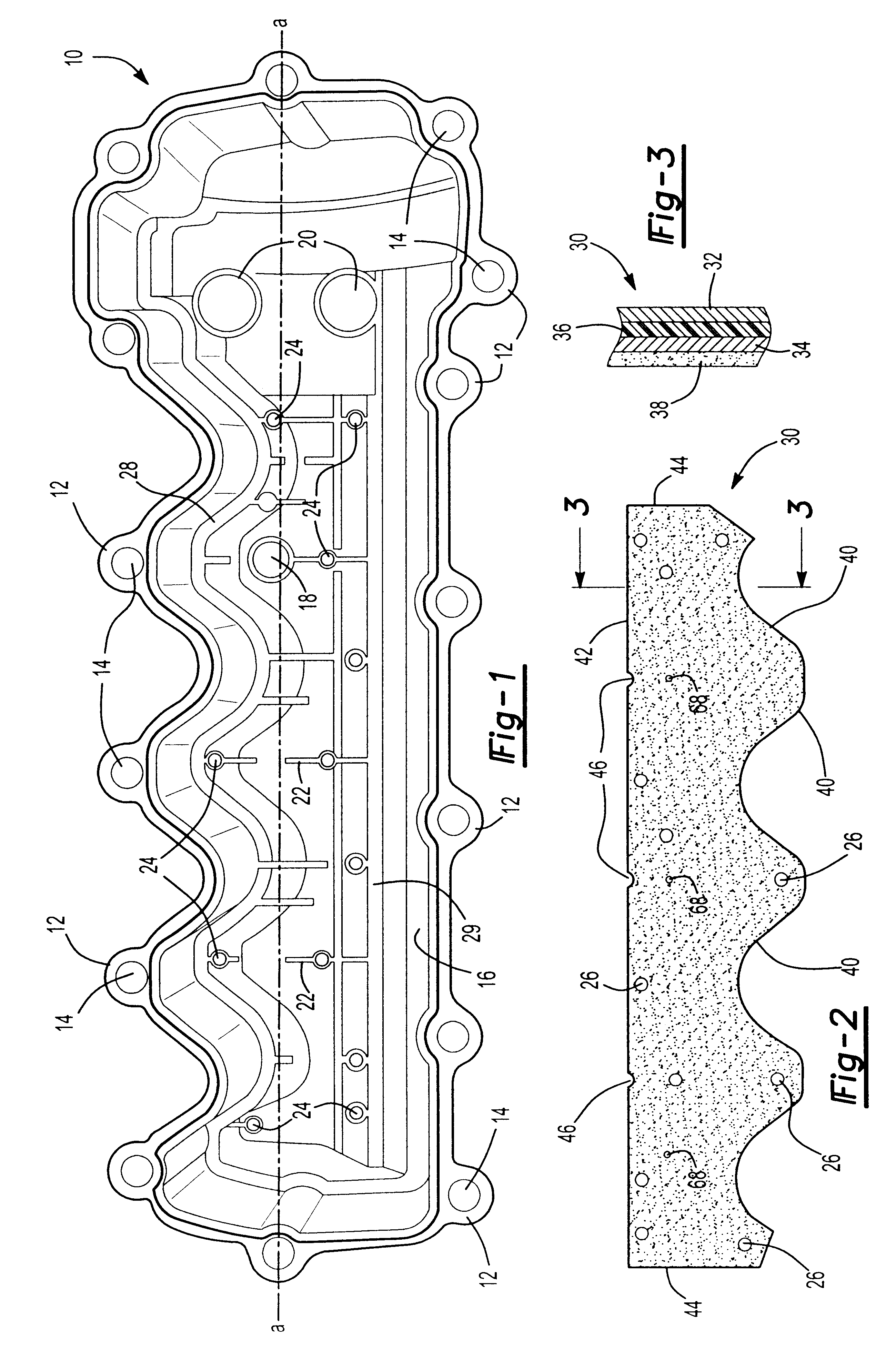
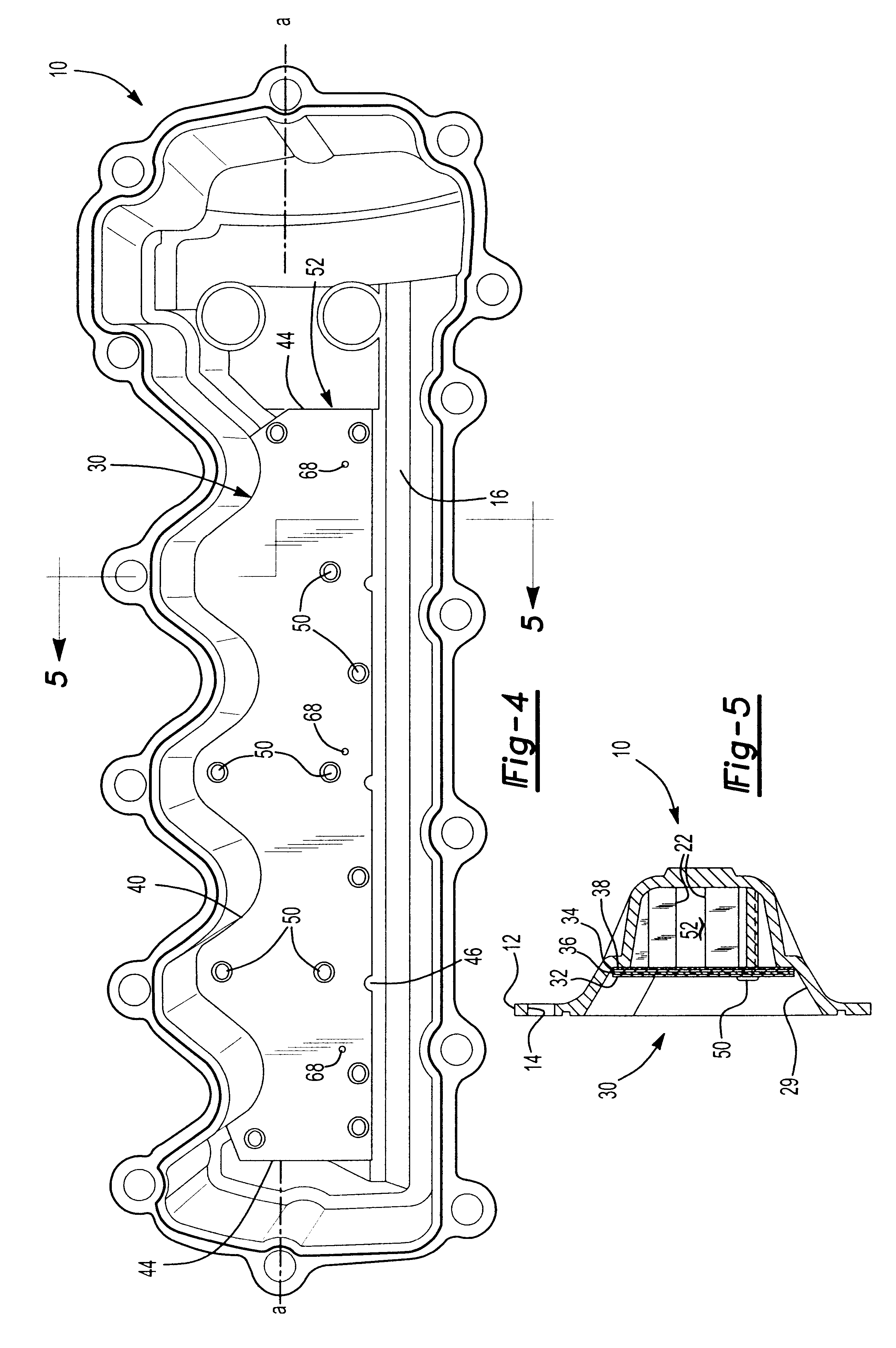
Referring initially to FIG. 1, an automotive engine cam cover 10 is adapted to be securely attached to a cylinder head (not shown). Such cam covers have traditionally been made of stamped steel, but in recent years have also been made of molded plastic, cast aluminum, or cast magnesium materials. The cam cover 10 of FIG. 1 is formed of cast magnesium, and has a longitudinal dimension that extends along an axis a--a, as shown.

The cam cover 10 includes a plurality of bosses 12 for attachment of the cover 10 to a cylinder head (not shown). The bosses 12 include bolt apertures 14 for said attachment. The cam cover 10 includes an interior body portion 16 that includes a positive crankcase ventilation (PCV) aperture 18, as will be appreciated by those skilled in the art.

The cover 10 incorporates other apertures 20 as shown, for accommodation of hardware unrelated to this invention, such as electronic apparatus including cam phasers and the like. A plurality of laterally (i.e. arranged tra...


PUM


Abstract

A damped steel baffle for an engine cam cover aids in separation of oil mist entrained in a flow of crankcase air vented through the cam cover, and directs the air to a PCV valve atop the cover. The baffle forms a channel for the air, and effectively absorbs noise generated within the cover. Oil droplets condense on channel and baffle surfaces, and drain to an engine oil sump. The interface between baffle and cam cover is sealed with a foam gasket layer or RTV sealant. The baffle is constructed of two metal layers joined together by a thin layer of viscoelastic adhesive that converts vibrational energy into heat to dampen resonant vibrations. Amplitudes of vibration are significantly lower than for plain steel baffles, hence lower sound radiation is achieved. The individual steel layers are 0.2 to 0.6 mm thick; the viscoelastic layer has a thickness up to 0.15 mm.

Description

1. Field of InventionThis invention relates generally to improvements in designs of baffles employed in automotive engine applications. More particularly, the invention relates to improvements in the manufacture of automotive engine cover applications, including valve covers, which are designed to reduce noise and vibration.2. Description of the prior ArtBaffles for automotive engine valve covers have been traditionally formed of a single layer of thin stamped metal, such as steel. Such baffles are used generally not only to aid in the removal of oil mist entrained in crankcase gases, but are also designed to optimize crankcase air flow through the valve cover.To the extent that the thin metal baffles have often been a source of noise, particularly as induced by engine vibrations, one recurrent theme with respect to such baffles has thus been the need for reducing such noise and for dampening vibrations. Several means of resolving the noise and vibration issues have been attempted; ...

Claims


Application Information

Patent Timeline
Patent Type & Authority Patents(United States)
IPC IPC(8): F01M13/04F02B77/11F01M13/00F01L1/00F02F7/00F02B77/13F01L1/46
CPCF01L1/46F01M13/0416F02B77/13F02F7/006F02F7/008F01M2013/0438
Inventor PLUNKETT, TOMSTAAB, TOMBOLDT, BRENT
Owner DANA AUTOMOTIVE SYST GRP LLC
Why Eureka
Try Eureka